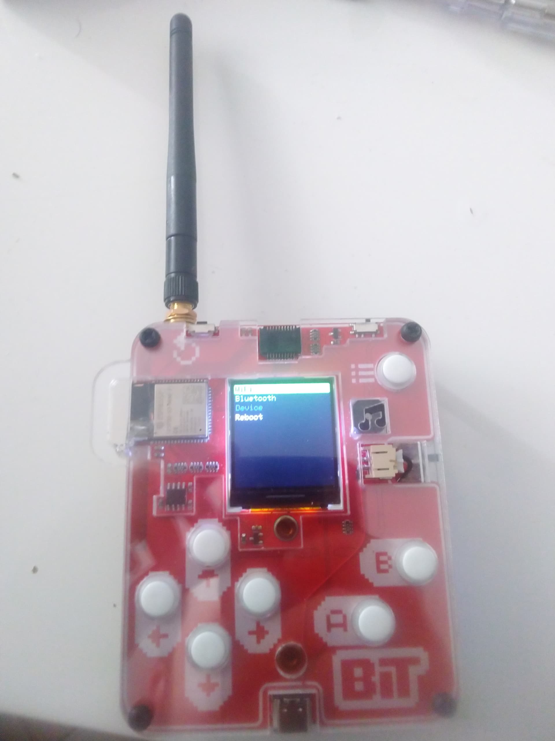
Hello, I just wanted to share a cool mod I did to the BIT. The following changes were made:
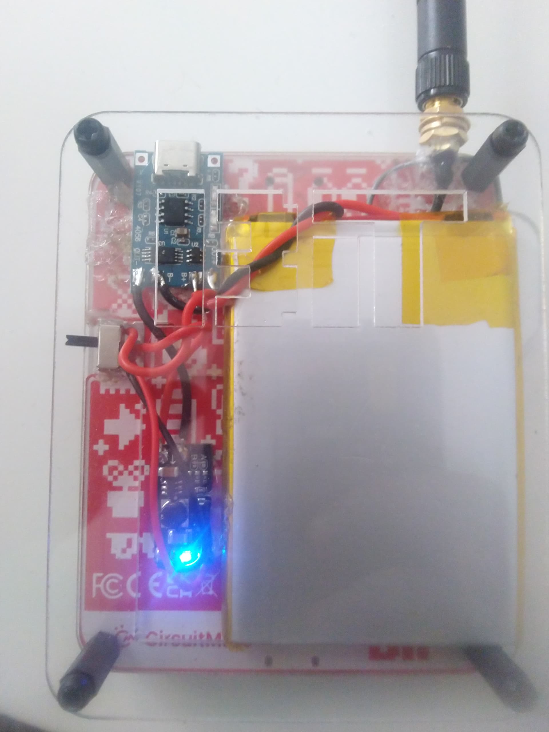
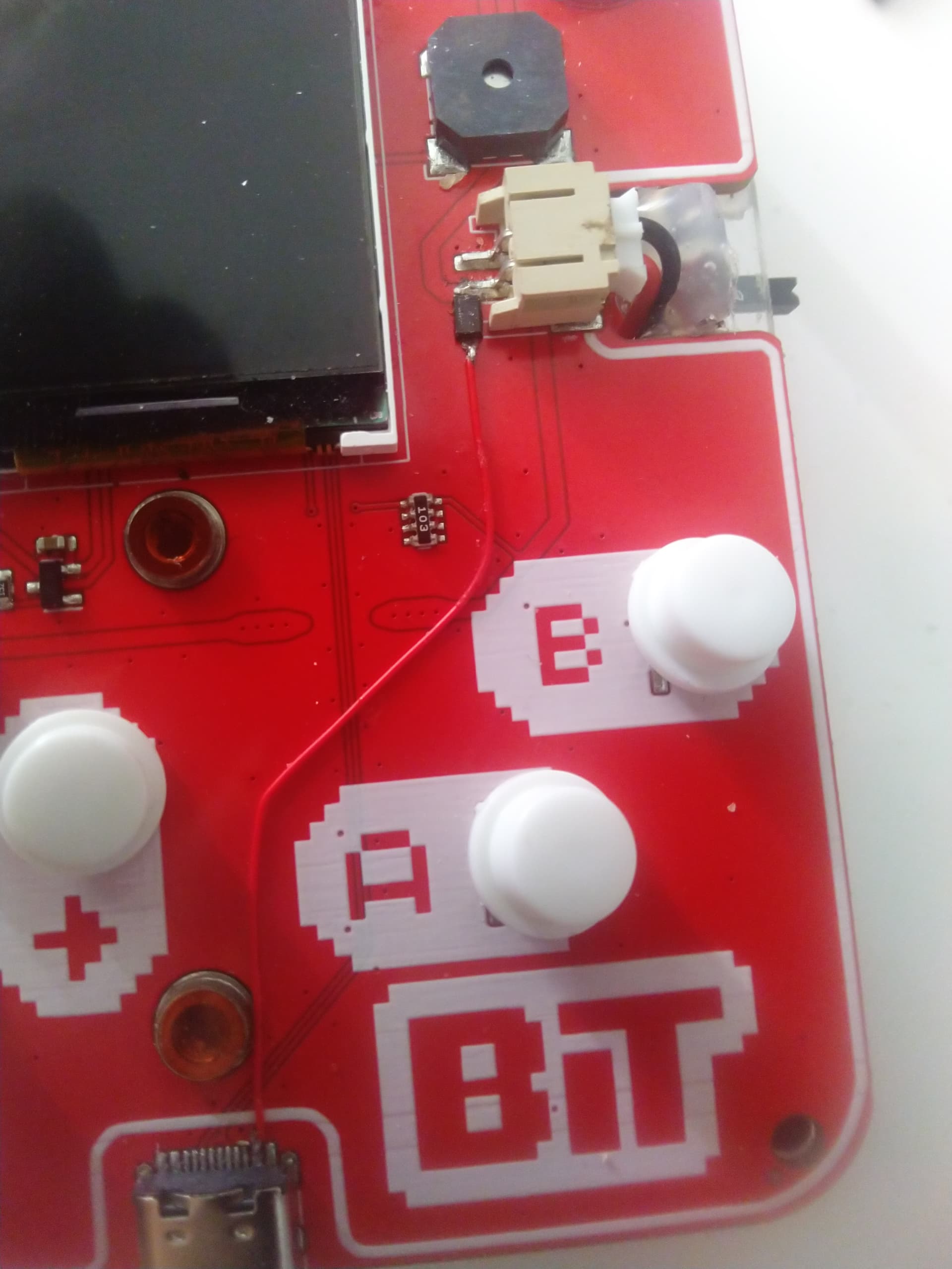
added a wire between the positive USB-C pin to the battery JST positive pin. This wire has a diode who only lets the current flow from the USB-c port. This mod allows powering the console using only the PC connection.
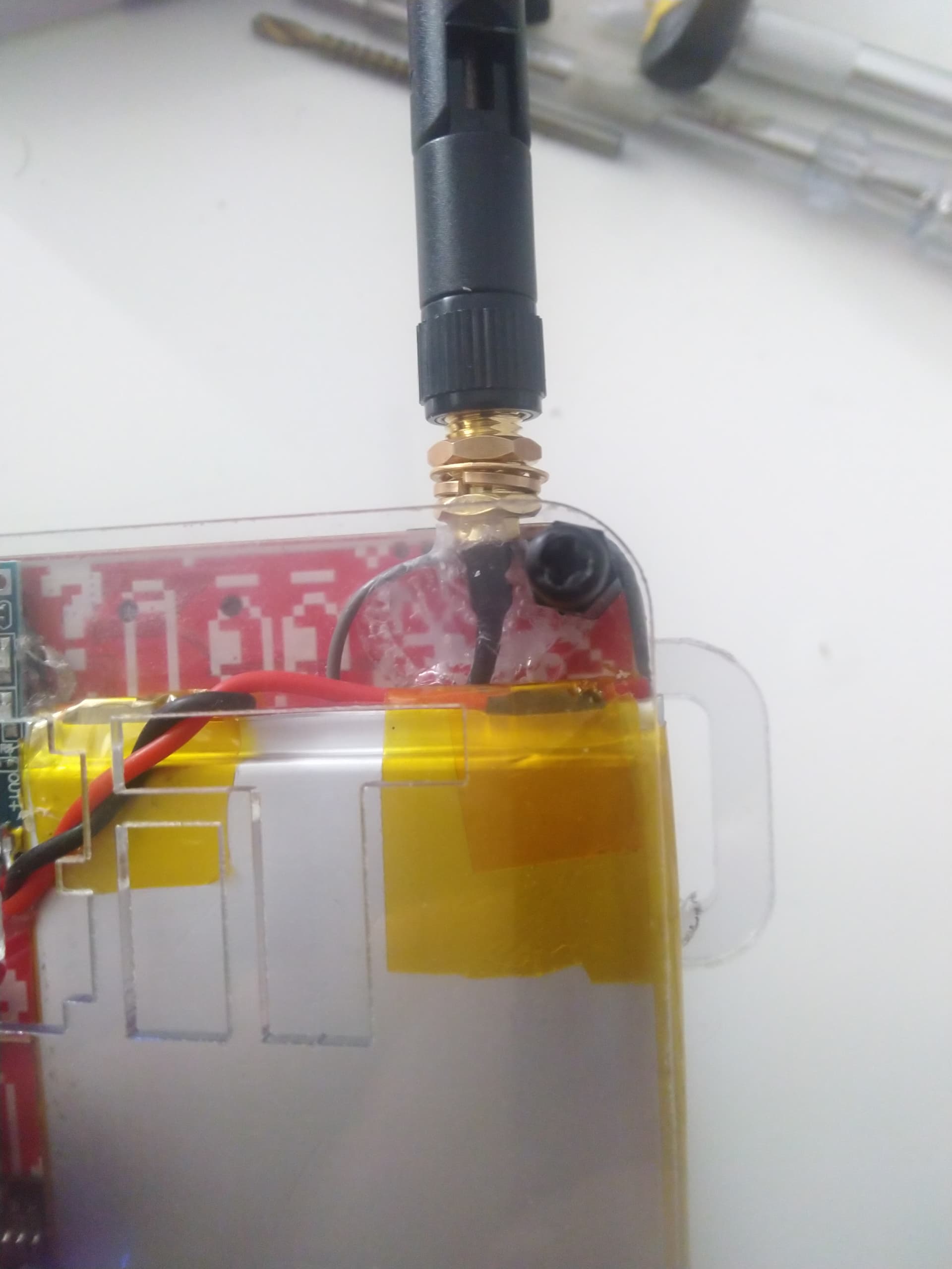
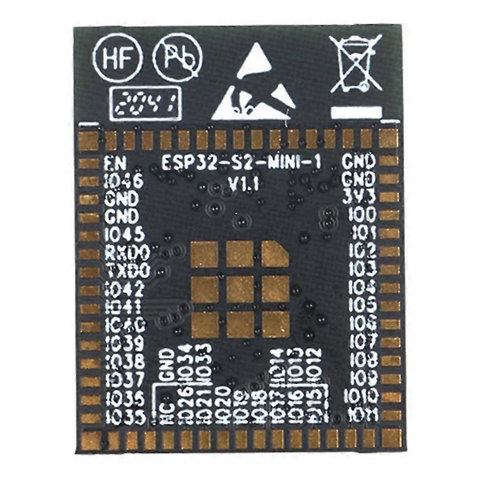
Added an external 2.4Ghz wifi antenna. By soldering the SMA to ipex cable to the ESP32 S3 Mini’s internal wifi antenna, this mod improves WIFI and Bluetooth range. The internal antenna’s traces had to be cutted to sepparate the positive and ground traces in order to support an external dipole antenna.
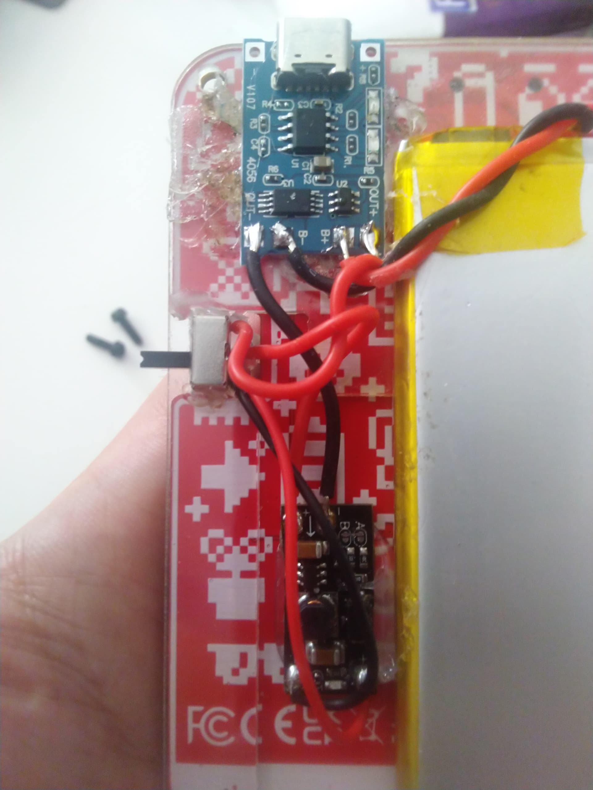
Replaced the 3x 1.5v battery holder with a 3.7V Li-Ion battery, a TP4056 battery charging module with discharge protection, and a 5V step-up booster module. A supplimentary switch was added in order to power on and off the board. The existing switch is also working but since the battery power is delivered to the JST connector, the additional switch was required to prevent any current draw when the console is turned off.
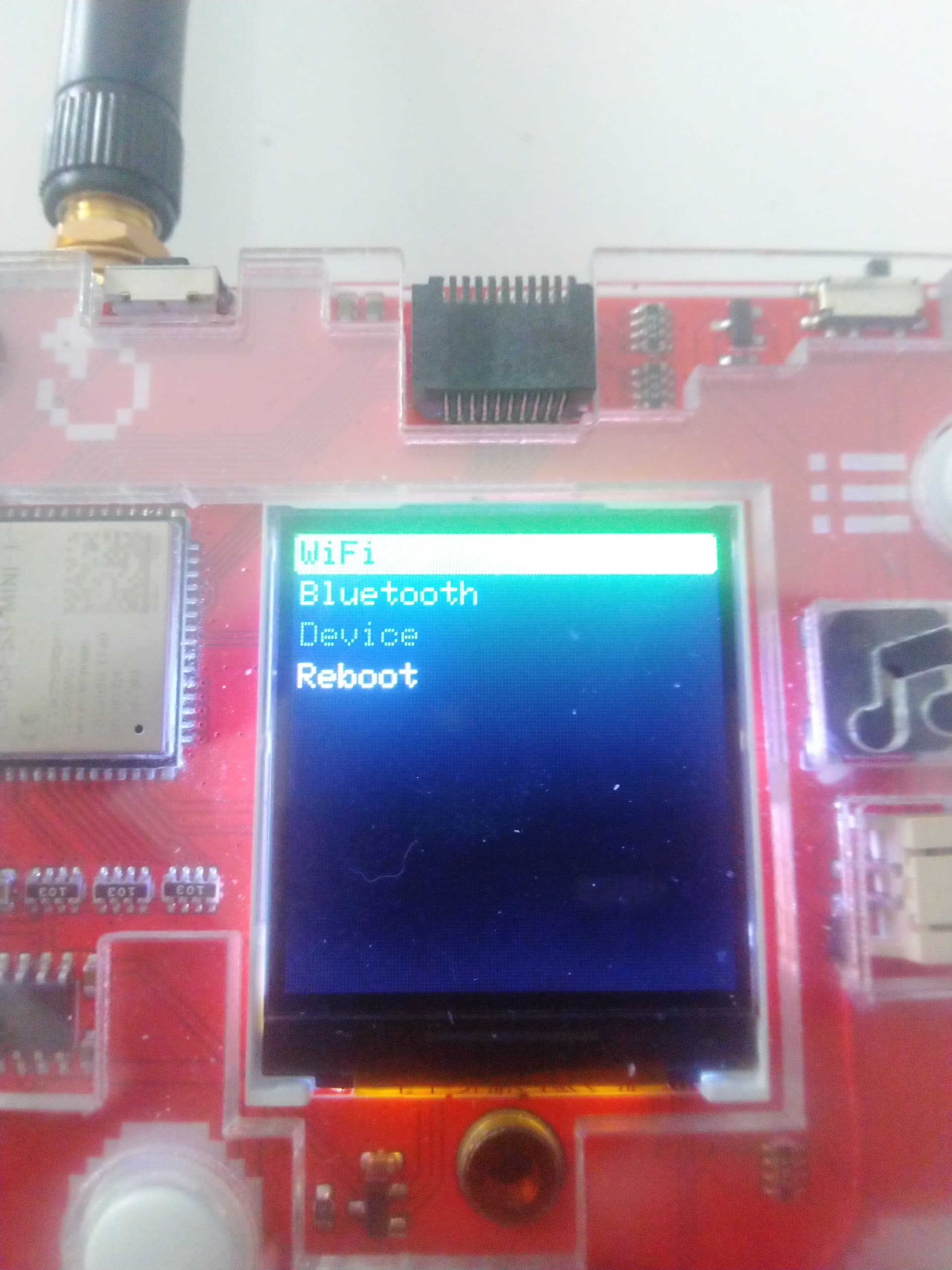
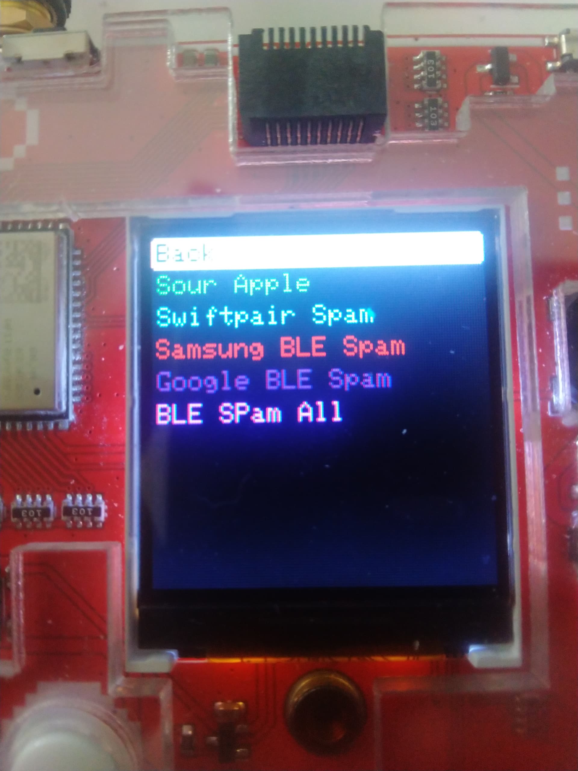
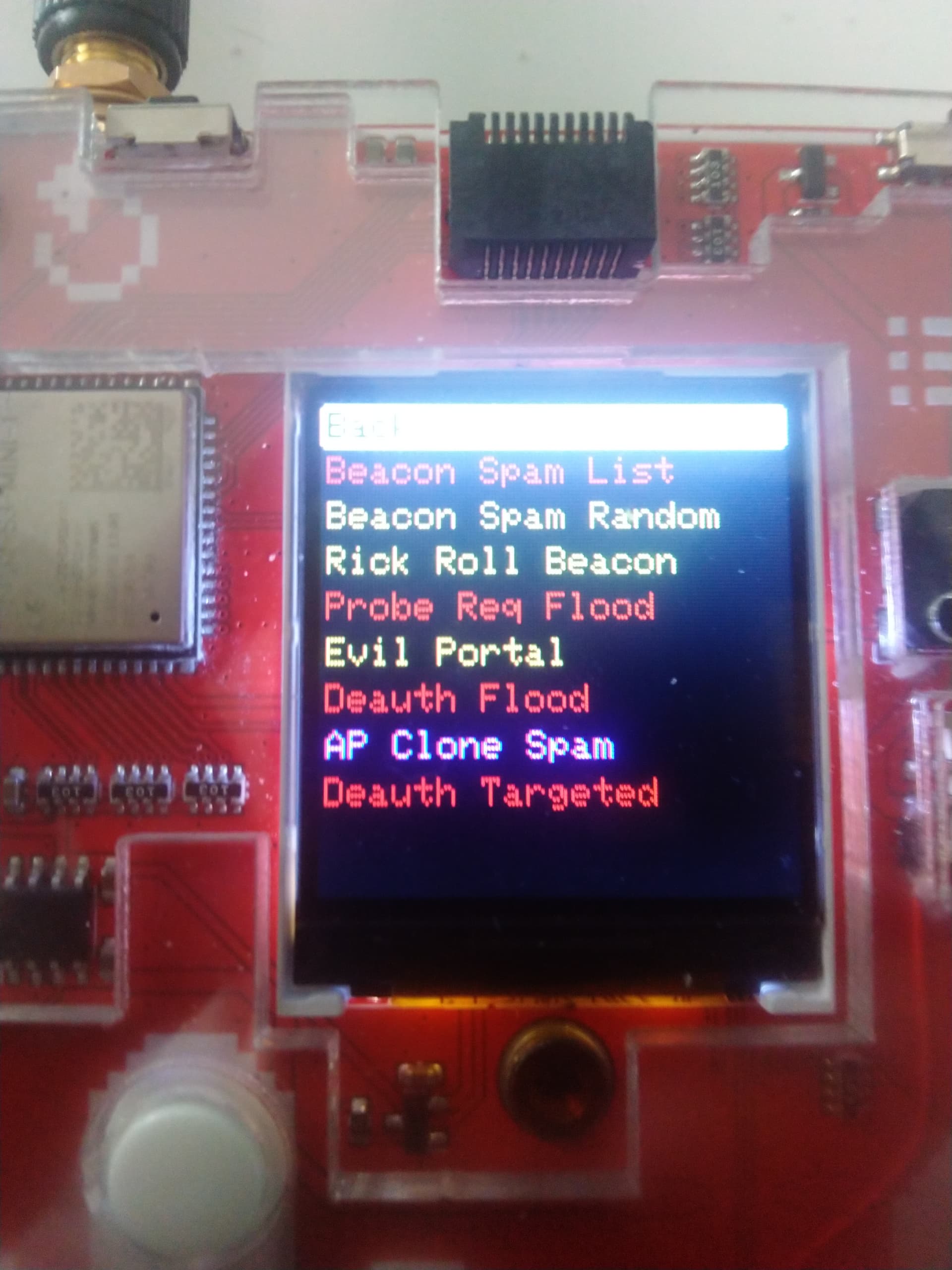
Flashed a customised ESP32 Marauder firmware that was specially tuned up to work with existing push buttons and use the TFT display’s pinout.
To be added:
-MicroSD slot
-GPS Neo-6M module
-custom PCBs that use the existing GPIO slot (for example: external modules with NRF24, CC1101, RFID etc)
Here at my BIT Console im trying to get pico OS Running, its not so good but once i get all the professional tools i will maybe show a instruction!
You can probably design a ui and maybe make a full tutorial, beacouse that would be great for all the people out there! Maybe Circuitmess considers making a actual PCB for this!
No. I just used Arduino IDE to upload the code into the esp32. The Esp32 Marauder is written in C++. The only changes I’ve made are the pins declared for the TFT display.
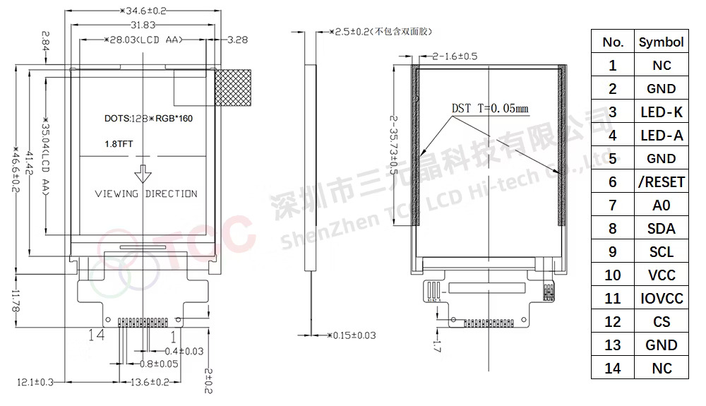
I had to carefully unstick the tft panel and trace all the tft pins continuity to the esp32. I couldn’t find a proper documentation of the TFT display pinout on the circuitmess website. I even asked for it and they did not shared such thing.
Even the BIT firmware is not written for Arduino IDE so I had to do the LoyanGFX stuff on my own.
Also, the BIT console did not power on when plugging in the USB port without turning on the battery too. So I had to add a wire between the usb port + to the JST + pin.
Also, micropython is not persistent in the memory, but my code is. I can reboot it and save settings and stuff.
Everytime i try using the original ESP32 on the BIT it doesnt work. Im pretty sure i have to use some esp tool to remove the firmware beacouse im pretty sure its like protecting me from flashing the firmware. Is it possible to somehow put a custom firmware WITHOUT making a bridge. By the way im pretty sure you can flash a esp32 with a battery.
I am using arduino IDE with esptool set up. I have also changed some of the compilation instructions for the Esp32 LOLIN D32, D32S2 and D32S3. the whole procedure of setting up Arduino IDE for this firmware can be found on the justcallmekoko’'s github page for esp32 marauder firmware. I’m not gonna link it here, it’s just one hit on google. It explains in the wiki tutorial how to setup esptool and configure arduino IDE.
And I am not using the battery. That wire I have added was to provide 5v directly from the usb-C port. It’s a shame they didn’t implemented such thing as powering on the usb.
Oh, that makes it more clear. Im trying to program a new firmware for the bit and make it public. Probably will be on github all i used.
Hope to see more upgrades!
Hey, i still didnt figure out how to use the display. It does show a white screen but it wont respond to any inputs. Can you maybe send me your intialization code to try running it from that? Thanks!