Found the solution, and it’s so simple. Just charge the battery until the red led turns blue. 
1 Like
 I did that and no luck.
And oddly, the problem gets a little better the longer I leave it powered up, and the battery voltage must surely be dipping slightly during that time. It’s slightly worrying that the LCD is from the unregulated battery supply and not from the output of the 3.3V voltage regulator. I suspect it’s a general instability of the LCD’s supply voltage rather than the absolute level that is causing the problem.
Jez
SOLVED (for me anyway).
I’ve cut the Vbat track to the display (just between C7 and the display socket) and linked the 3.3V line to the display supply pin.
The difference is astonishing. No flickering and the contrast is rock solid and doesn’t change over time.
1 Like
Amazing. I will do this too!
Hi,
Do make sure that the track is properly cut, I used my multimeter on continuity setting to check that there was no continuity between the capacitor and the LCD connector (pin 6). Then I added the link between pin 7 of the Atmel and the supply to the LCD pin 6.
After switching on I made sure I measured 3.3V between pins 8 and 6 of the LCD connector.
Contrast is certainly more stable.
Jez
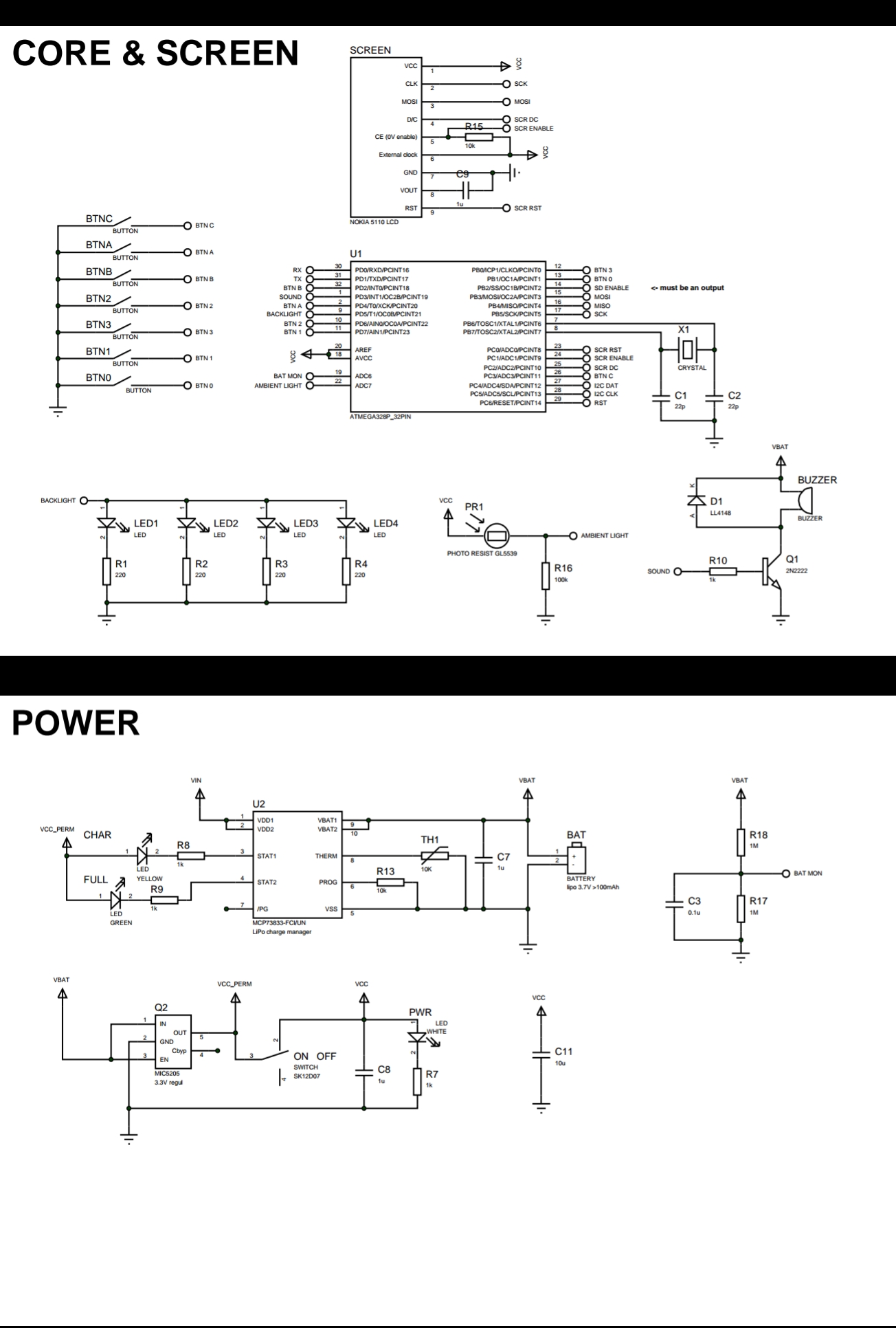
Interestingly, the schematics for the GameBuino show that the LCD supply is taken from the regulated 3.3V rail. The Makerbuino schematics however show that the LCD supply is taken from the unregulated battery rail.
MakerBuino
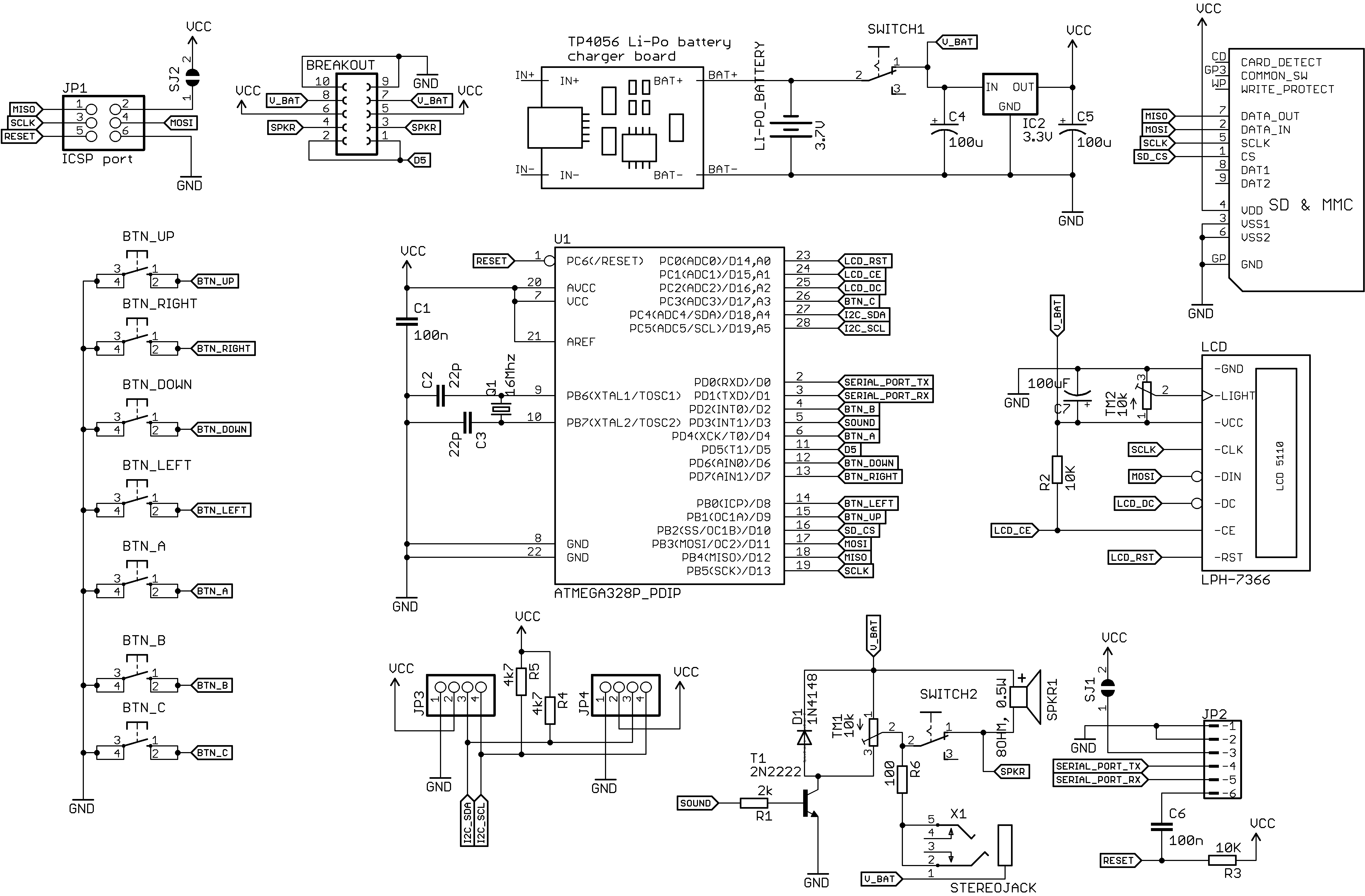
GameBuino
Jez,
What is it i need to do. this is all new to me.
Hi Ian, I will try and produce a step-by-step guide for carrying out the modification, hopefully this evening.
All the best,
Jez
EDIT: Since I have carried out this modification, I have seen a problem with contrast return (although not so erratic). So on balance I do not recommend that you do this. More investigation is required.
Hi all,
Here is a step-by-step guide to fix the LCD contrast problem that may be caused by the LCD getting its supply from the battery rather than from the voltage regulator.
Please note, this worked for me. I can’t however accept responsibility for any damage caused if you try this and it doesn’t work out for you. I will of course do my best to assist you in any case.
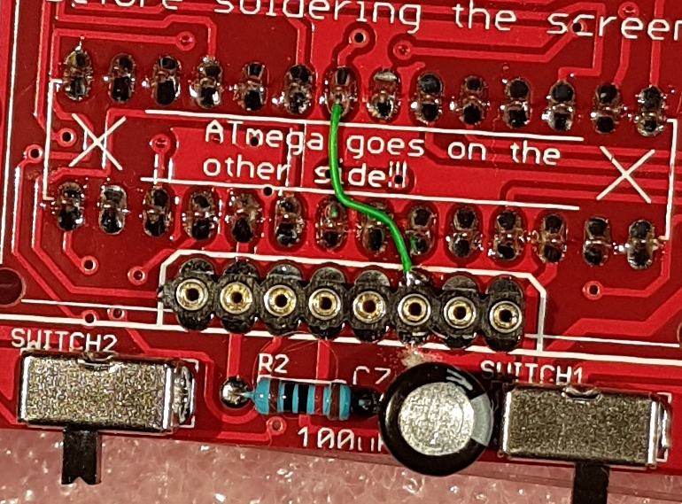
Step 1. Remove the display.
Step 2. Using a new sharp craft knife, carefully cut the track that goes between pin 6 of the display connector and the capacitor C7.
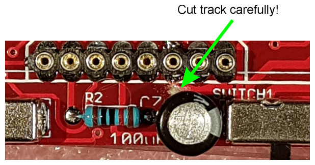
Step 3. Check that the track is fully cut by placing the display on the connector, switching on your MakerBuino and see that the display does NOT turn on. It should be completely blank. That means that you have cut the track correctly.
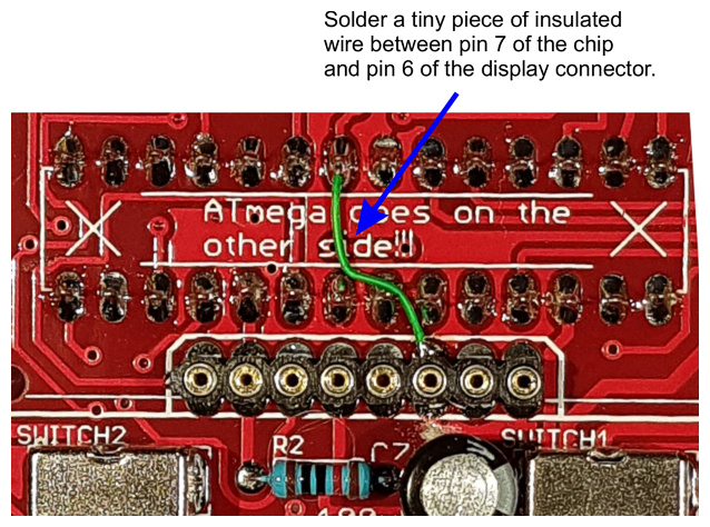
Step 4. Solder a short length of wire (stripped by 1mm at each end and then tinned with fresh solder) between pin 7 of the chip and pin 6 of the LCD connector on the board (not the connector itself!).
Take great care not to join solder to the chip pin that is very close to the LCD connector.
Step 5. Now place the LCD back on the connector, power-up and check that all is alive. You may need to adjust the contrast settings, but you can do that after you have fitted all the screws etc.
I hope this helps people who have a working MakerBuino but are not able to get a stable contrast.
This mod will ensure that your display gets a regulated 3.3V supply instead of the rather variable battery voltage (about 3.3V to 4.1V). For me at least, it helped with the erratic display contrast. If you use a multimeter on the DC volts setting, you can check the supply voltage that your display is getting by measuring between pin 8 and pin 6 of the LCD connector.
Please don’t try this mod unless you accept that you may damage your beloved console.
All the best,
Jez
EDIT: Since I have carried out this modification, I have seen a problem with contrast return (although not so erratic). So on balance I do not recommend that you do this. More investigation is required.
1 Like
My contrast changed over time. I left it for a while and the next day it came up all dark. I guess I will have to do what you did.
Hi JacksonNg,
Mine is definitely better after the track modification, and since I’ve swapped the LCD for a new one too it’s improved the contrast still further (although I’m not keen on the blue backlight!) As a matter of interest, I’ve seen the LCD module available on quite a few “maker” websites, worth checking out.
Keep us updated on how you get on.
All the best,
Jez
1 Like
Great job. I will do the mod and report back.
1 Like
@Jez, thank you for your effort in this and for helping the community out. I will reward you with a couple of badges.
I’ve seen your post about this quite some time ago but I was struggling with finding some time to investigate this and reply to what you’ve been doing.
Here goes:
The screen is supplied with the unregulated battery voltage on purpose. I’ve changed this compared to Gamebuino’s original way of connecting the screen to fix the problem of screen flickering due to the noise produced by microcontroller’s oscillation (which is quite ironic since this seems to be the source of your problems).
Usually, I fix these problems by sending a new screen to the user.
I personally test every Nokia screen before sending them to the users (in other words, I’ve tested over 3000 of these screens) and the main thing that I’ve learned is that they’re a massive pain in the ass.
There are 20% defectives in every batch, regardless of the supplier.
And the worst part is the fact that they sometimes decide to die out of nothing or due to transportation/moisture/temperature/soldering mistakes.
The biggest problem is actually caused by the conductive rubber between the screen and its board. Dust and other unwanted particles come between the rubber contacts and the board’s metal contacts and cause contrast problems, which can sometimes be fixed by cleaning the contacts.
@eskimo explained what’s happening with the screens quite good:
This post of yours got me quite confused as this is a unique case of someone doing this to fix the screen. Usually, the problem is caused by dust between the rubber contacts.
What was causing the problem with your screen - I don’t actually know…
Maybe your screen is in some way different or there is something different on your board (some defective component) which I don’t see.
As you can see, people are building their MAKERbuinos successfully and the problem is not in the PCB design, the voltage level on the screen is supposed to be that way. If it was wrong, all MAKERbuinos would have that issue (and they don’t have it, we’ve sold 2500 units so far I am quite sure about that).
Anyways, kudos on figuring this out and sharing your experience in a forum post.
You’ve motivated me to find a solution to the defective screen related problems so I’ve managed to source a different version of the Nokia screen.
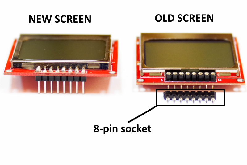
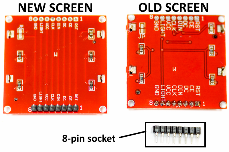
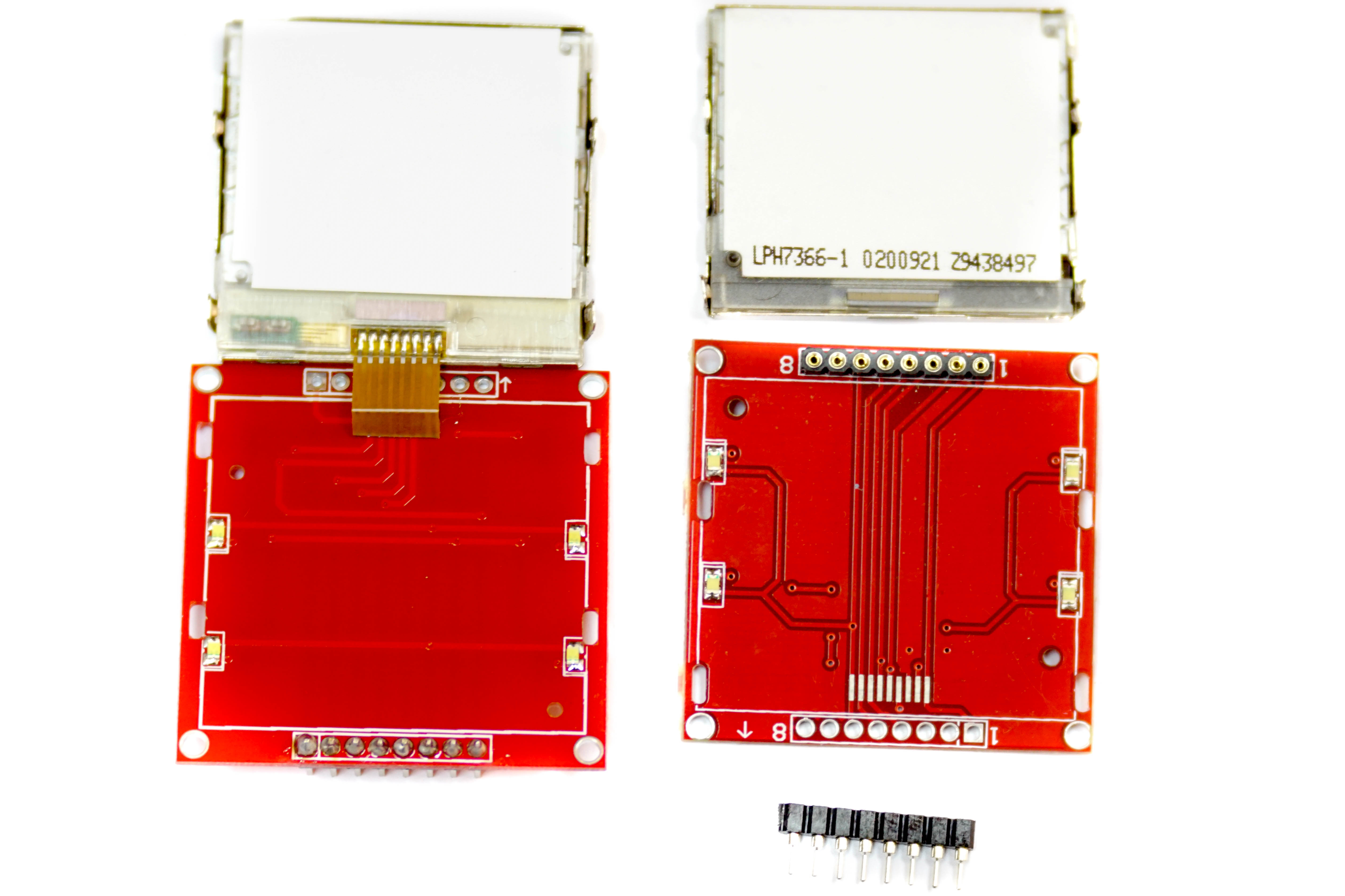
This new version of the screen has a piece of presoldered flexible cable that is connecting the screen to the red screen module PCB instead of the conductive rubber. This version of the Nokia screens has fixed contrast settings (you cannot change the contrast), are a bit bigger, clearer, have better refresh rate and look quite better in general.
Also, we’ve decided to remove the machined header socket with a pin header that is soldered directly to avoid problems with connection.
These new screens are now shipped with every new version of the MAKERbuino.
1 Like
Interesting, will this cause problems where people won’t be able to alter an undesirable contrast or is the Makerbuino designed in a way where the contrast will now be at a standard ‘ideal’ level across all new units?
1 Like
@Dalemaunder, that is a great question!
The contrast will be constant and at a “standard” ideal level across all new units.
Although this doesn’t have anything to do with the MAKERbuino, the MCU will still try sending contrast commands to the LCD, but the new LCDs don’t respond to that command because of some reason.
It seems that the Chinese are somehow “locking” the screen at a certain “optimal” contrast level.
I’ve tested this on quite a few units in the past weeks and I am sure the contrast is constant.
Also, about the better screen quality I was talking about:
A great example is @Bl4ckM4ch1n3’s MAKERbuino that is among the first ones that came with the new screen
You can actually compare the screen of his MAKERbuino with the other ones in the topic and see that the screen has the same dimensions but a larger drawing area and its contrast is much better compared to the older screens
1 Like
@Dalemaunder, also, I am still testing every screen personally to ensure that they actually are working well, have no dead pixels and are actually locked at that “ideal” contrast level
1 Like
I think I might have a similar issue although my screen is blank. The backlight and sound work though.
1 Like
@Cheryl_Court, is the screen completely blank or just very dim? If it’s completely blank, then it has nothing to do with the contrast issue.
Please open a new thread or write to contact@makerbuino.com and attach some pictures of your device’s front and back side without the casing.
Ah, okay, will do. The screen is completely blank other than a couple dark lines around the border. Everything else seems to be working as far as I can tell. I’ll open another thread or send an email, thanks.
1 Like