Going to upload the device pics soon.
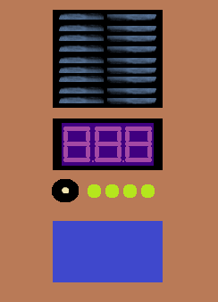
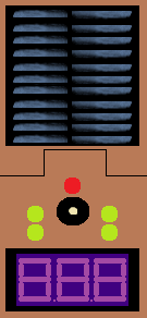
Here are some drawings of the concept.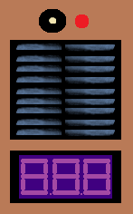
1 Like
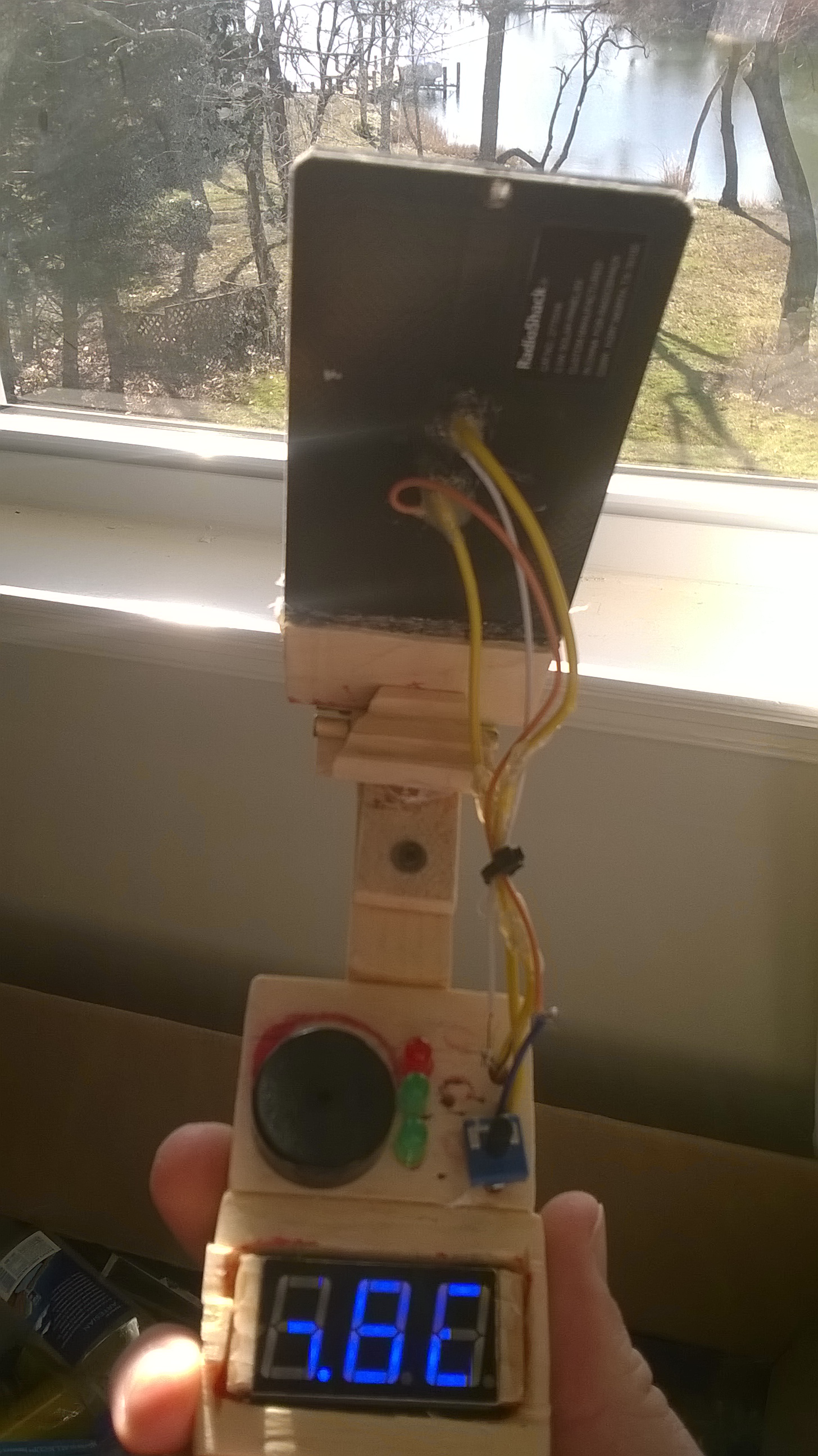
This picture shows the concept for the tool. During testing, it was found that the panel was not enough to power the vmeter. So for now, this is just a great idea that went south.
I’m currently developing a new illustration for a slight improvement. The panel will flip out. Think about the Enterprise Communicator, but the lid is the panel. I haven’t decided on whether the panel is the lid or facing the bottom.
A lid seems easier and ergonomical.
2 Likes
That’s a pretty cool idea!
What are your plans for upgrading it? Bigger solar panel or something else? 
1 Like
I did. The prototype Model A wasn’t working out too well. It’s been modified since then.
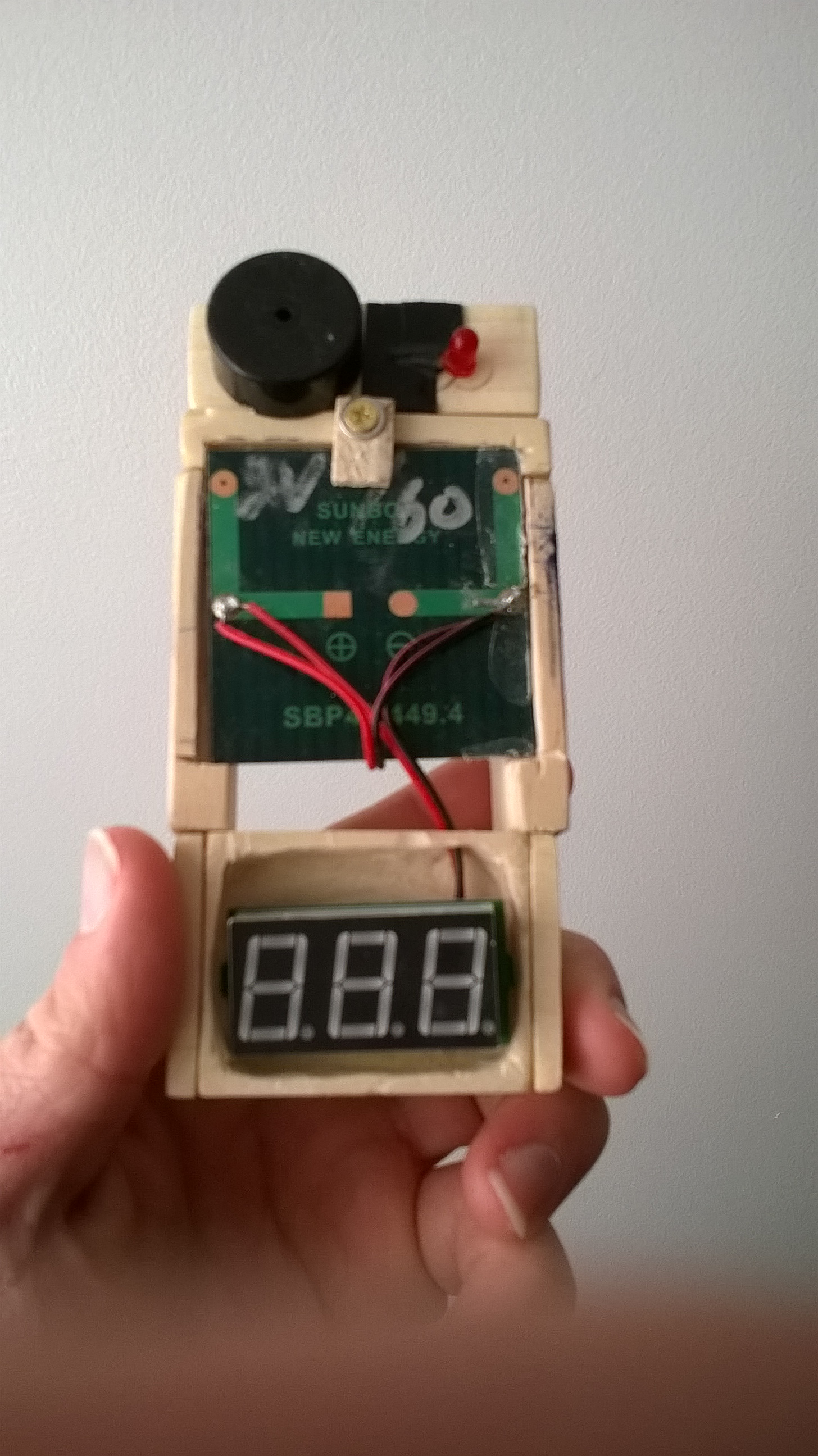
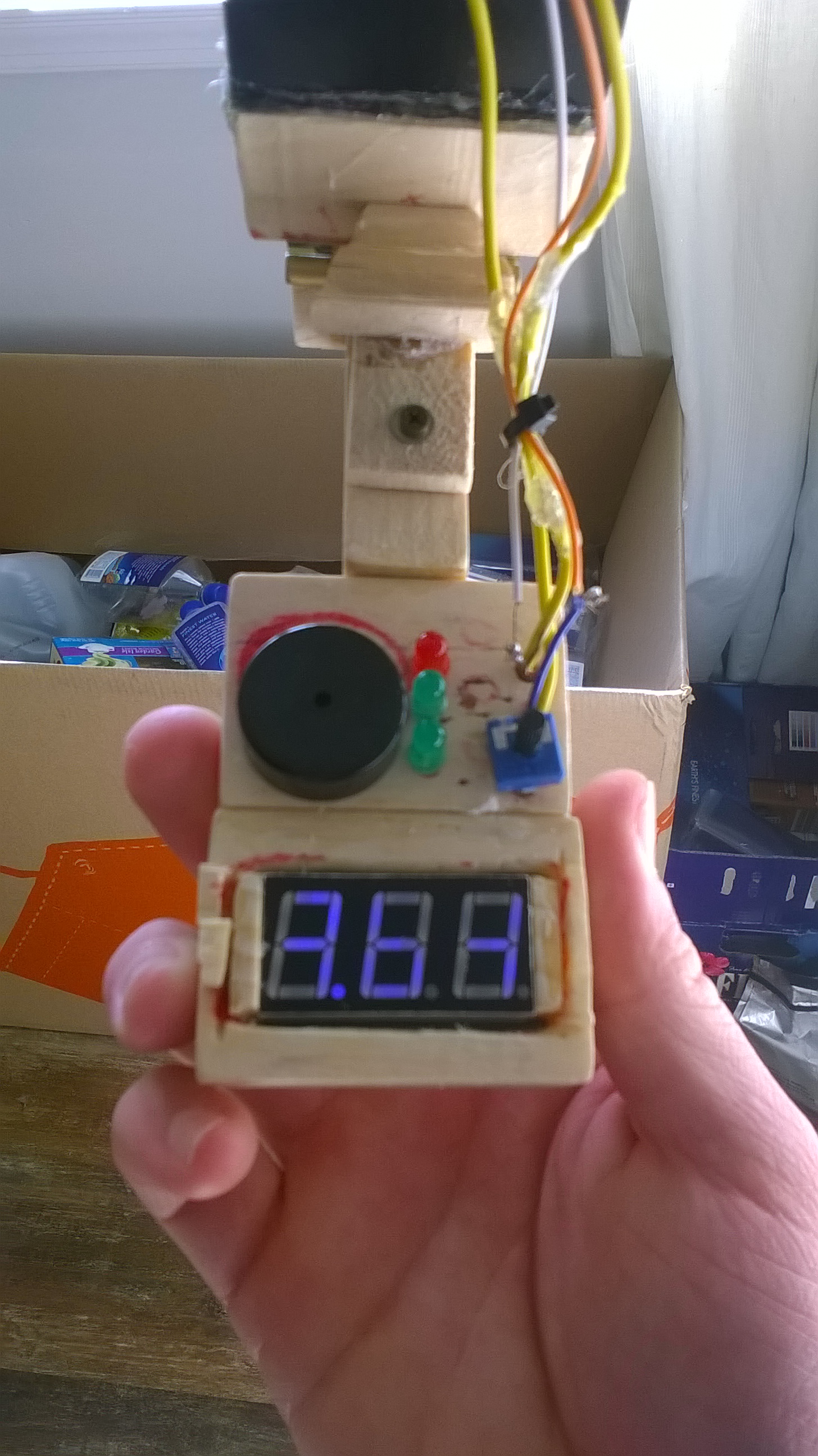
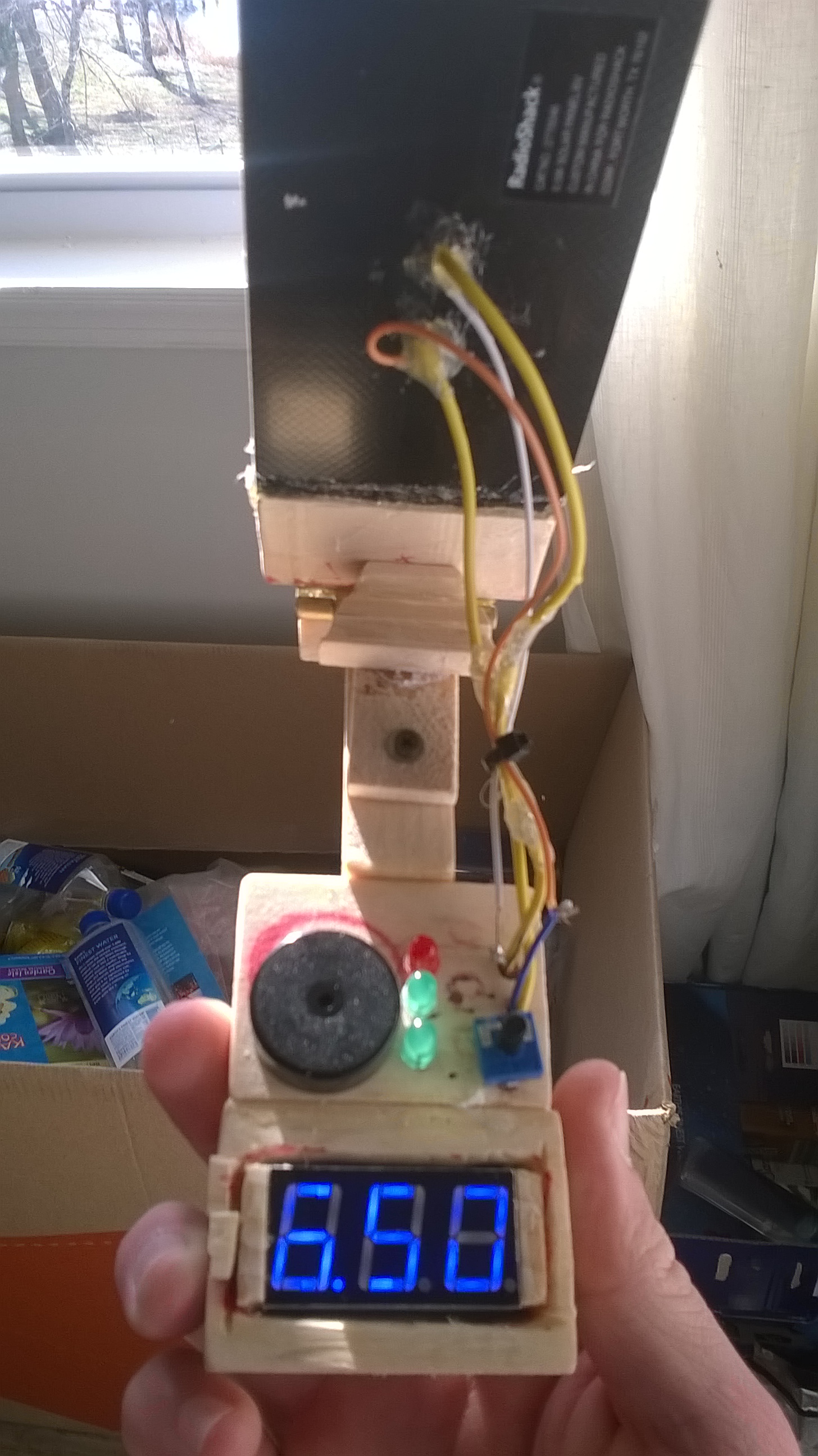
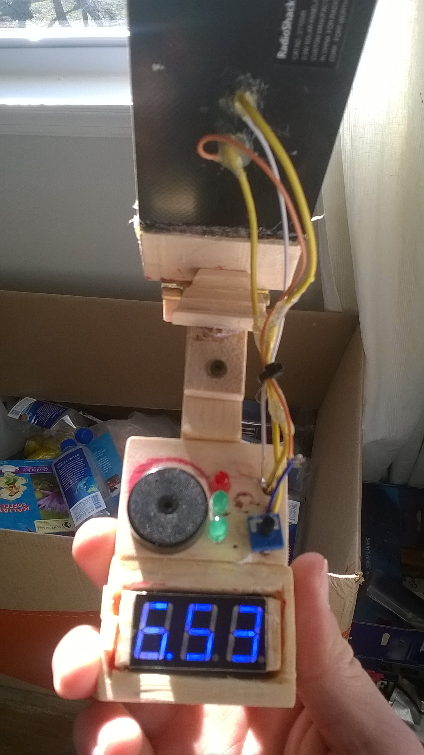
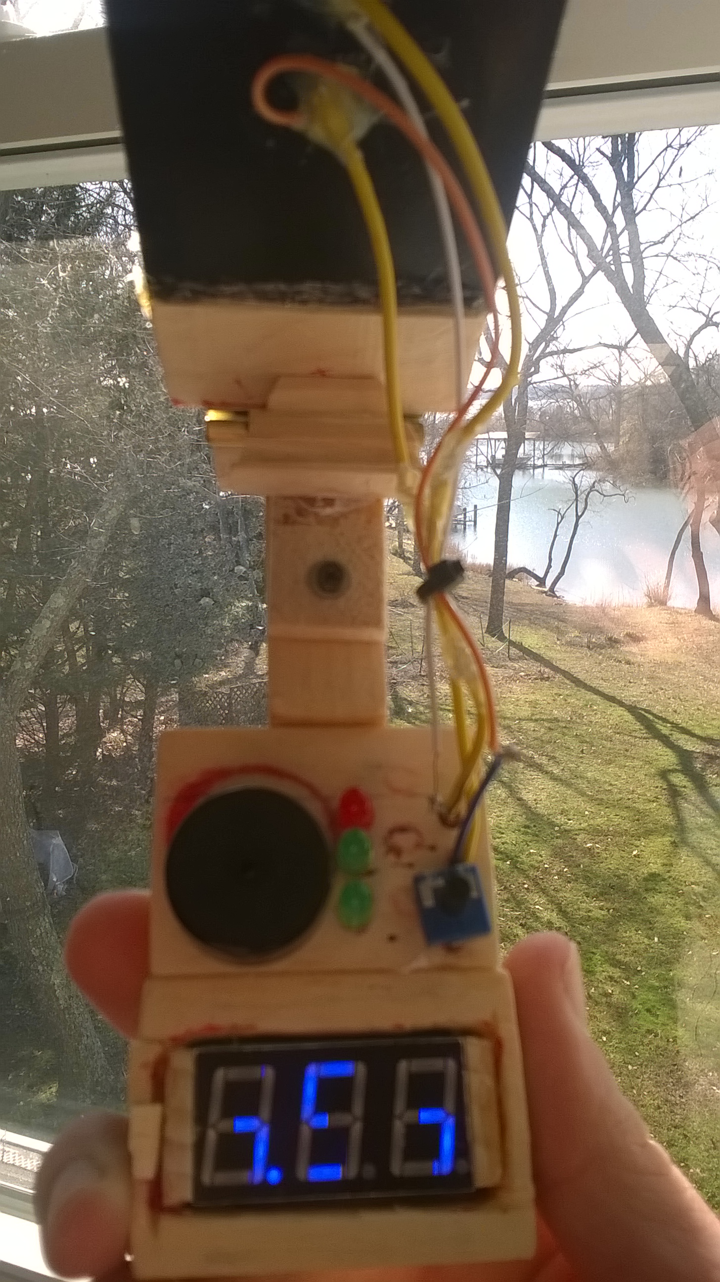
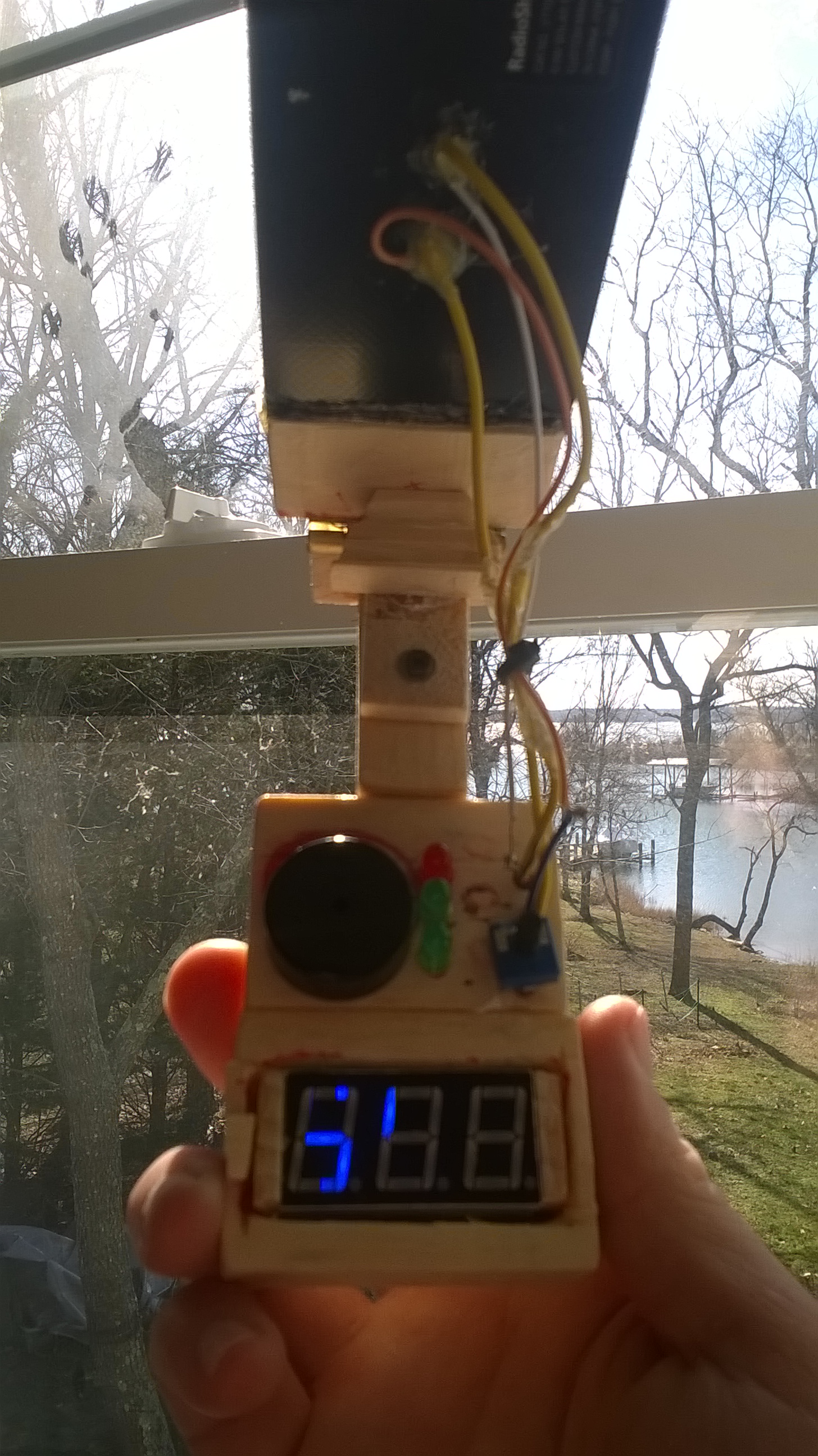
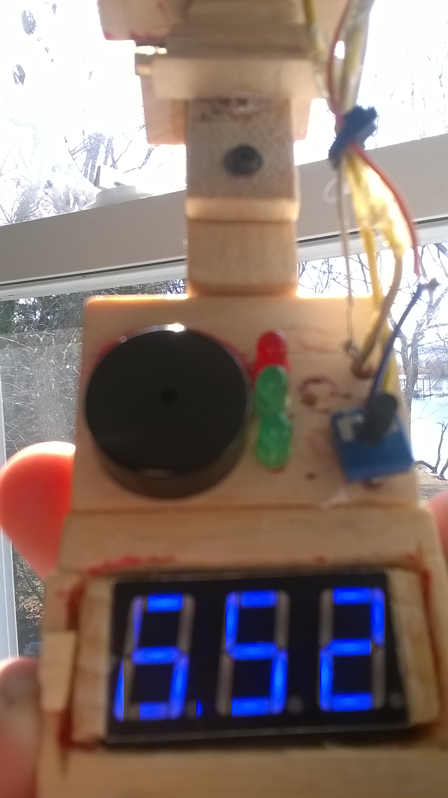
All the different uses and examples. These are the test photos for them. I will be taking one last photo of the finished variant after I install the last part.
1 Like
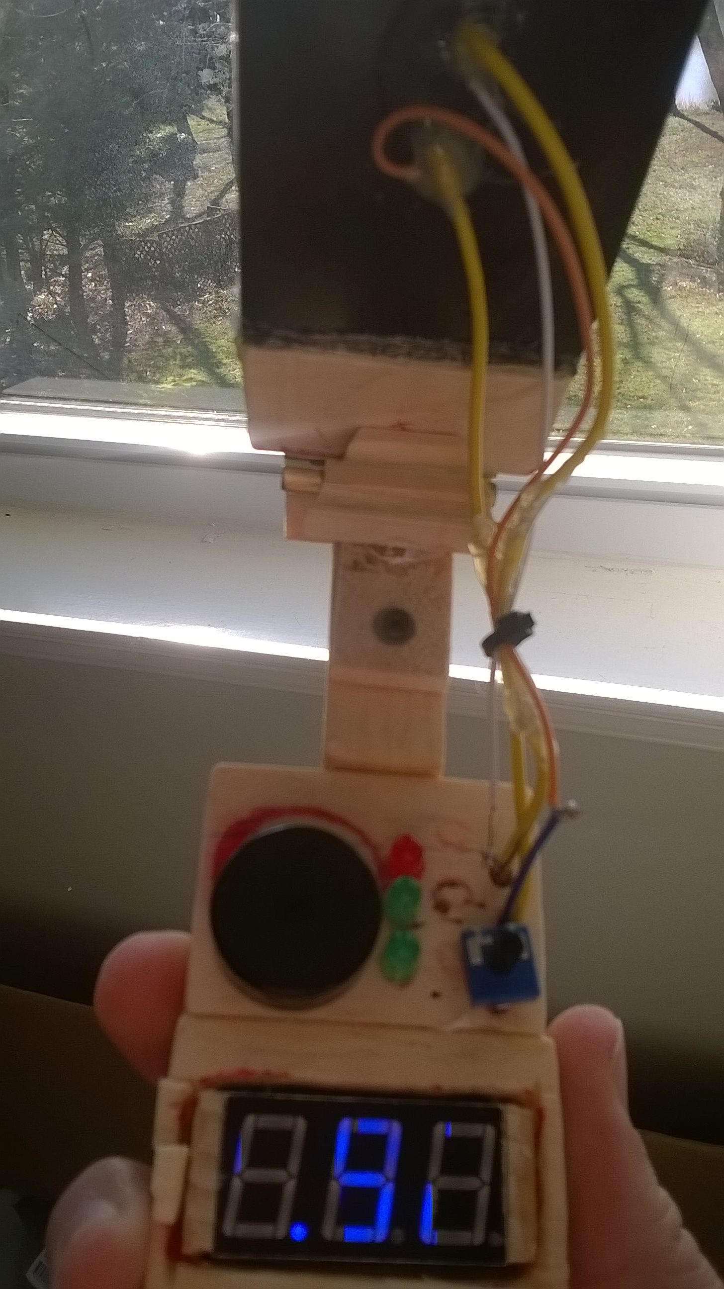
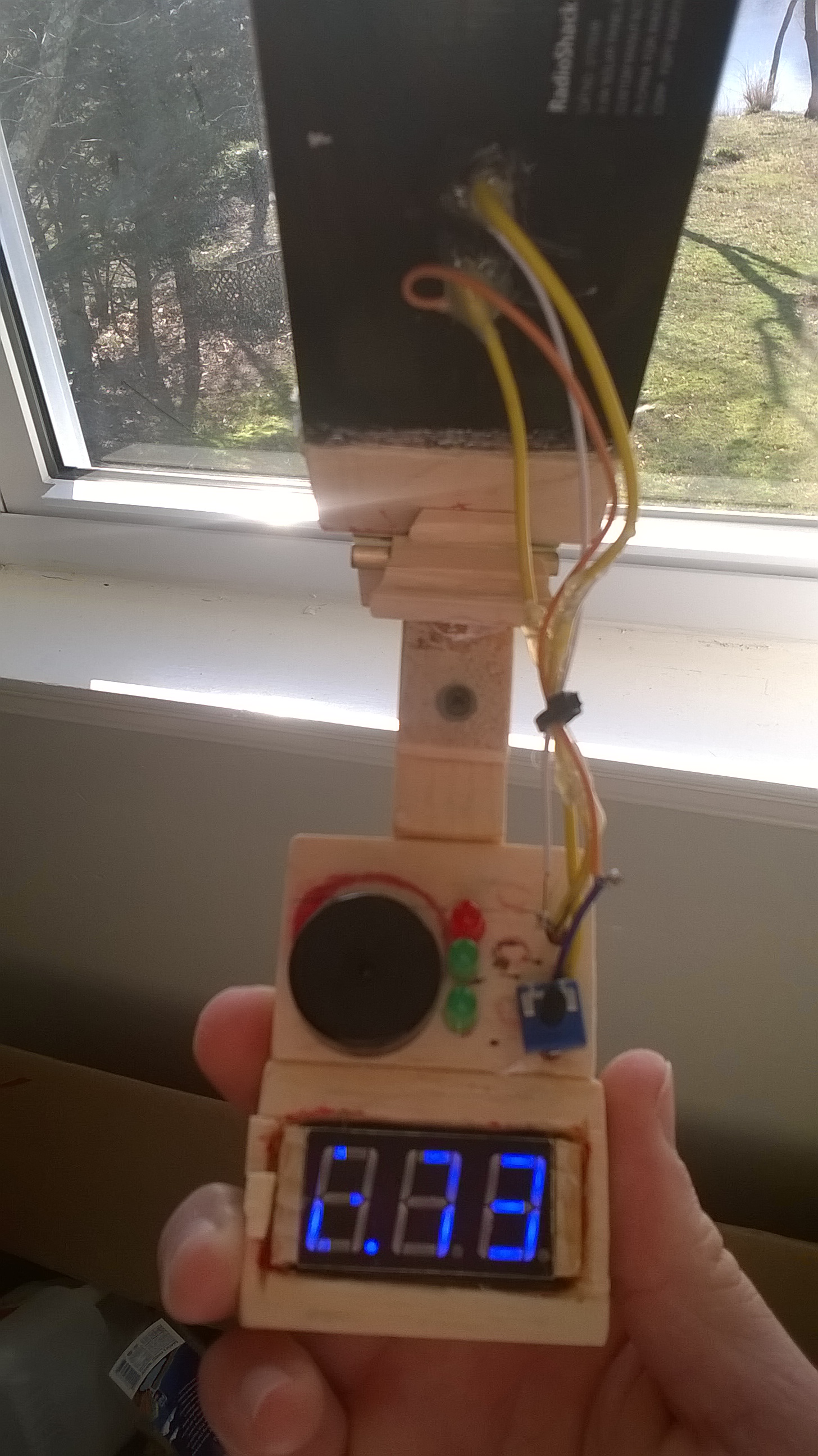

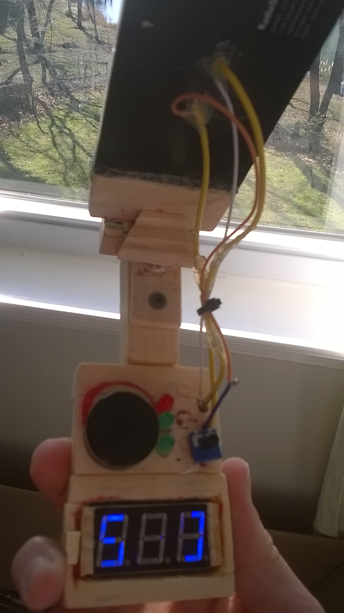
Comments:
The meter was not well adjusted because of the design. A final assembly would not sit so close to the bottom. If made, it will be covered by a plate and screwed against a well seated meter. The vmeter was not adjusted before reassembly. I believe the connection shorted - which I solved by separating wires to opposite ends of the meter. Only a screw driver will be required to screw the plate and adjust the meter.
You CAN use this meter for
-Finding sunlight
-Testing strength of sunlight
-Accurately determine the IO of vcc from your ((project)) panels.
You should NOT use this for
-Testing accuracy of large I or V
-Testing large I or V from larger diaphragms
-Modify the meter for larger diaphrams
This meter is just a small tool for personal projects. You can most definitely make your meter and use it for small personal checks and balances when you’re outside. I don’t recommend it, but if you’re putting a panel up you’re only looking for sunlight. Just don’t hook anything up to it. It’s a .5w 6V panel on there.
Seems like you put in a lot of work into that.
Were you able to do anything with the received energy?
Did you try to do some battery charging as well?
It would be interesting to know if this little panel can be used for effectively charging a small battery!
Robert
1 Like
I can see where we’re heading there. That actually wasn’t related to the initial design.
This captures my vision by shadowing the concept tool.
I did think about what people would expect from the tool. That’s why I made it very clear from the beginning what would be expected from what model.
This solar tool is used to measure the available sunlight.
I have two other concept designs. The second and third work in a similar way to each other. The Model B will have a breadboard. The Model C will have an output jack. What makes the model C and B different from A is the toggle switch. Just like like the potentiometer on Model A, a toggle switch will separate contact from the available sensors. There will be a place to draw power from the panel on Model C. The toggle switch will similarly turn off the power from the breadboard on Model B.
1 Like
I want to update everyone on this project. It has become a side project again…due to other updates.
Since my post, I have updated the models forms. The wood designs will now be modules that connect through pins. The pins make contact, and then you glue them together with clear loctite.
The new vmeter module design doesn’t use solder. That means the meter won’t break by heat or contact. A cover plate screws to the bottom of the module.
I probably won’t be revisiting the project for a few months unless I get bored.
Let me know if you have any questions or requests or something. I’ll try to help you as best as possible.
1 Like