if the nes used c/c++, how hard could the port be
I found this link: https://www.instructables.com/Arduino-NES/
I tried to make it work by mapping the correct pins but I could not get past the “out of memory” errors. Don’t know why they happen for allocations of 32Kb since from what I saw, Ringo should have a maximum of 520Kb
Hello!
Looking at the tutorial, it uses the TTGO T8 ESP32 dev board which has an additional 4MB SPI ram chip. Unfortunately, the Ringo doesn’t have one and only has the 512kb ram supplied on the ESP32 itself, of which about 250kb remain available after FreeRTOS and other components are loaded, and that seems to not be enough for the emulator.
You can use the ESP.getFreeHeap() function to get the remaining ram available at any point during the program execution.
Happy tinkering,
Filip
Ah, thanks. That explains the out of memory errors. The code had plenty of logs regarding mallocs and I guess they all summed up exhaust the 512 KB then (because I wasn’t counting the memory used by global variables and such that appears while compiling. Kinda forgot about those).
@filipCM Might be a stupid question (because I understand more about programming than circuits) but is it possible to add RAM to it somehow? By soldering something extra or such?
I’ve just checked with our hardware dev, and unfortunately, it isn’t possible to add an SPI RAM chip to the Ringo brainboard. Currently, the clock pin is connected to the UART connection for the SIM module, and the rest of the ESP32 pins that are required for the RAM aren’t connected to any brain board pins.
If you have some soldering skills, you could solder the RAM wires directly to the ESP32 microprocessor, but then you’d lose calling and SMS features of your Ringo. You could technically solder the pin that is going to the SIM module to another pin of the ESP32, but then you’d have to modify the firmware to actually use that pin.
You can find which pins to connect, as well as Espressif’s official documentations on external RAM on the ESP32 here: https://docs.espressif.com/projects/esp-idf/en/v3.2.3/api-guides/external-ram.html#hardware
And here are the schematics for all the boards on the Ringo: https://github.com/CircuitMess/CircuitMess-Ringo/tree/master/schematics
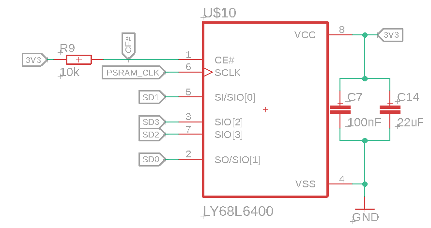
The chip we use and have determined works quite well, is the LY68L6400 4MB RAM chip. Here’s how we connect it:
On the software side, if you do solder on the RAM, you would also need to modify the compile options and add a define to enable the usage of external RAM, and, if you’d like to retain the calling capabilities with the new hardware, recompile the firmware and use that from then on. The compile options are located in the Arduino15/packages/cm/hardware/esp32/1.1.0/platform.txt file. Specifically, the ringo.build.defines option is used to add additional defines. To enable external RAM, add the following defines:
-DCONFIG_SPIRAM_SUPPORT=1 -DBOARD_HAS_PSRAM=1 -DCONFIG_SPIRAM_USE=SPIRAM_USE_MALLOC -DCONFIG_SPIRAM_USE_MALLOC=1
And then, in your setup() function, psramInit() to initialize the external RAM. You can use psramFound() to check if it’s detected, and ESP.getFreePsram() after it’s initialized to check the free space to make sure it’s detected correctly.
The Arduino15 dir is located at C:\Users\<username>\AppData\Local\Arduino15 on Windows, ~/.arduino15 on Linux, and /Users/<username>/Library/Arduino15 on Mac. Ringo’s firmware source code is located at https://github.com/CircuitMess/CircuitMess-Ringo-firmware .
Happy tinkering! 
Filip
Wow, that seems too advanced yet for me but thanks for all the info. For sure it might help people with more skills (and maybe I can return to this later on too). Thank you @filipCM
@filipCM Okay, I’m tempted to try this out but I have some questions:
I’m a noob in relation to electronics and I want to learn how to read those schematics (since I recently got into electronics as a hobby). Could you point me some good online resources to learn about that? Because all I could identify was that there’s a resistance of 10k between the 3v3 pin and the CE#…
I searched for the LY68L6400 but all I could find was LY68L6400SLIT which has 8M x 8 and not 4MB. Would that also work?
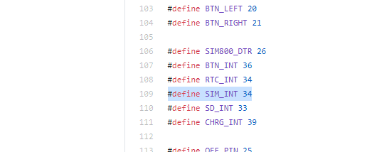
Regarding the change on firmware, it seems to me that the digital pin that refers to the SIM card is SIM_INT on MakerPhone.h. Is that correct?
And at last, when changing the compile options, what do I need to do to recompile with them? Just restart Arduino IDE and compile as normal?
Thank you for all the support (and patience) so far