For those who want to customise their backlight colour, here’s how you do it. Note that if you already have assembled your MAKERbuino, you need some decent (de)soldering skills.
First remove the front and back panels. Desolder the connections on the bottom side of the mainboard. Not the ones at the LCD side. You can use a handheld vacuum pump (AKA solder sucker  ) or if you have access to it, a vacuum soldering station.
Remove the metal bracket by bending the 4 lips outward. Depending on your LCD module there might be a zebra strip, connector or flex cable, connecting the LCD panel to the board. Be careful not to rip or break anything.
Next remove the LEDs. I just used a large blob of solder on my soldering tip to heat both cathode and anode at the same time and then gently wiping the LEDs off the board.
Clean up the pads and solder the new ones. I used Super Red OSRAM LSR976-NR-1 LEDs. But any 0805 LED will do. Note the polarity of the LED. On my module the cathode was the upper pad in the picture below. Cathode of the LED is usually indicated on the bottom side of the substrate.
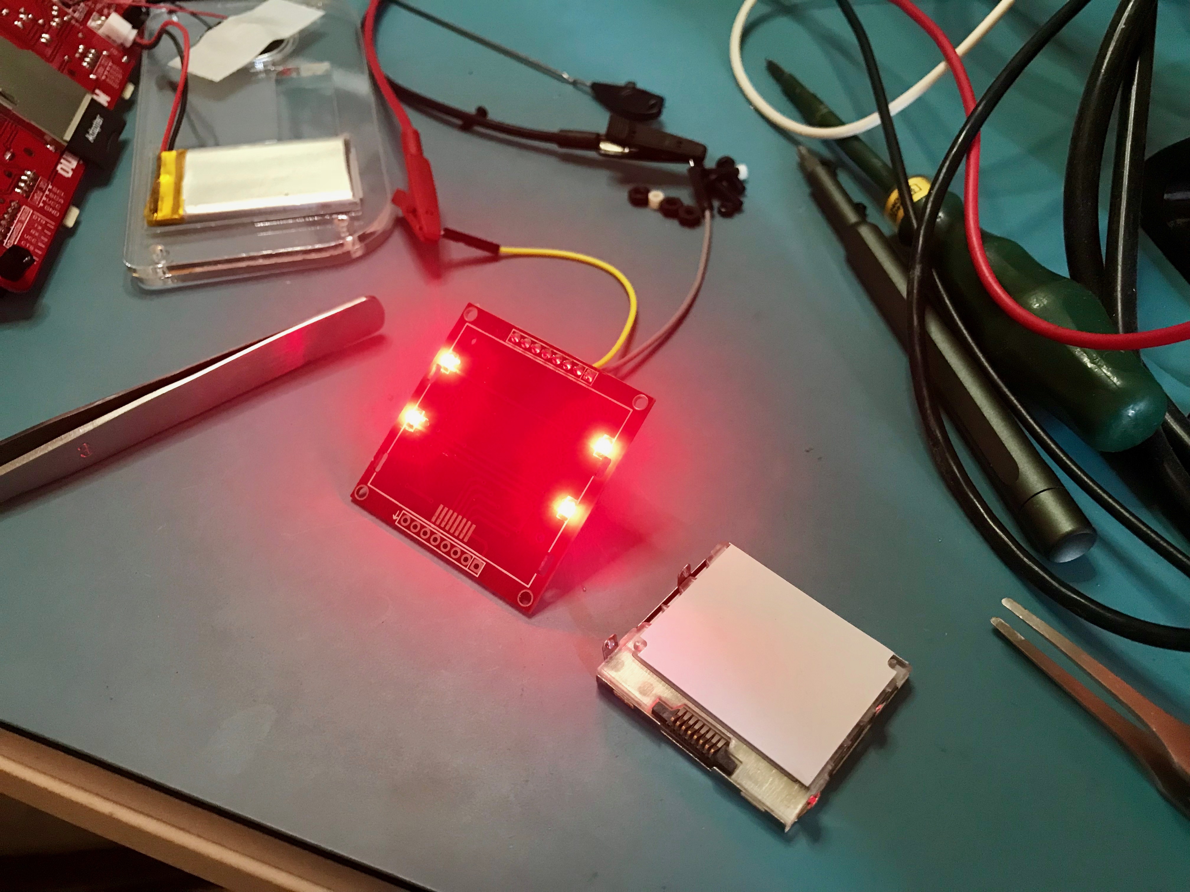
If in doubt, start by replacing a single led. Connect power (somewhere between 3 and 4.2V) to VCC and ground of the power supply to LIGHT and the LEDs should light up. Do not connect the GND of the module because you don’t need to power the LCD controller itself.
My series resistors are 150 ohm, so that is also good enough for a red LED. Due to the lower forward voltage, the current through the LEDs will increase from around 32mA for four white LEDs to around 60mA for the red ones (15mA per LED). But there is plenty of juice in your battery
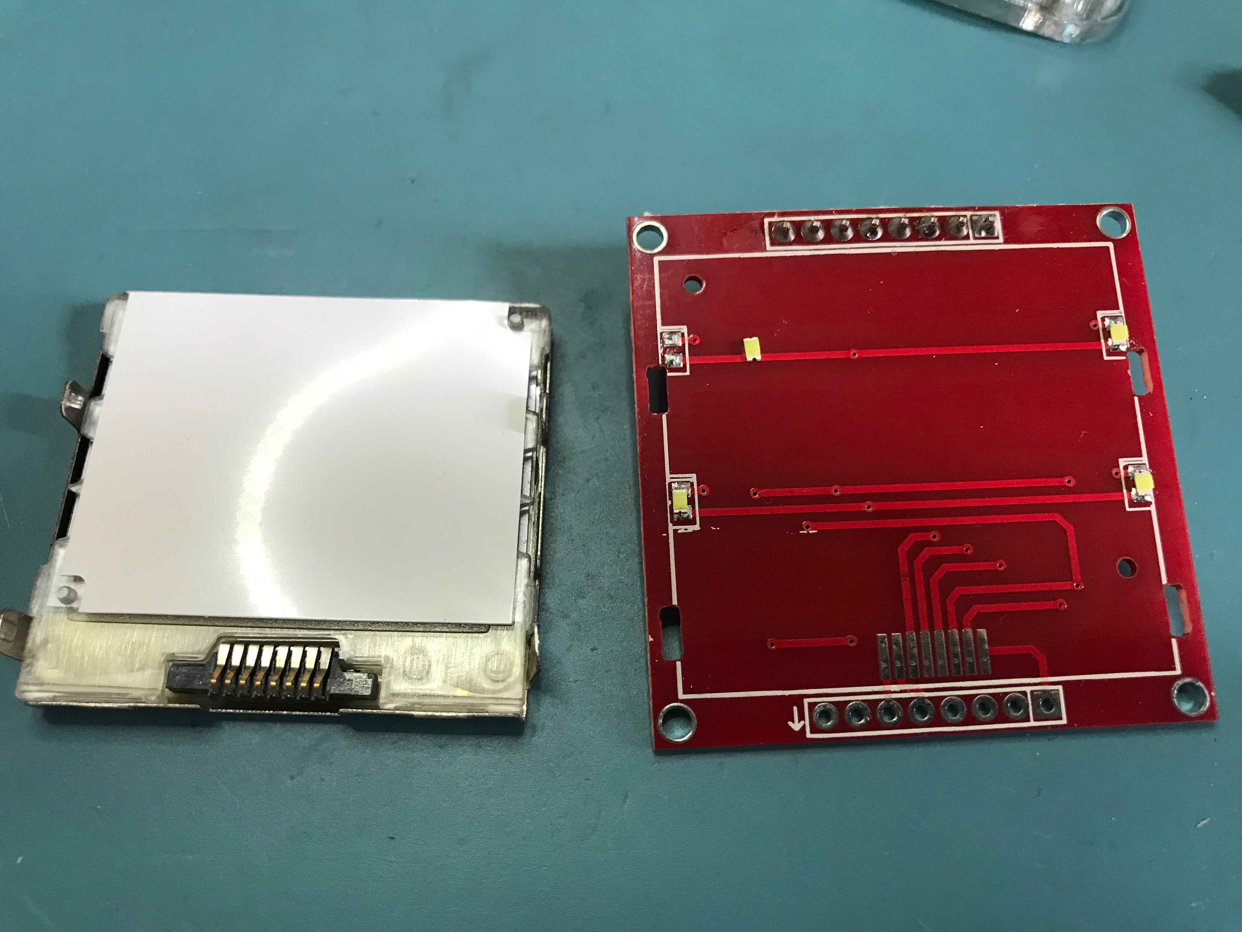
Bracket and one LED removed.
New LEDs installed.
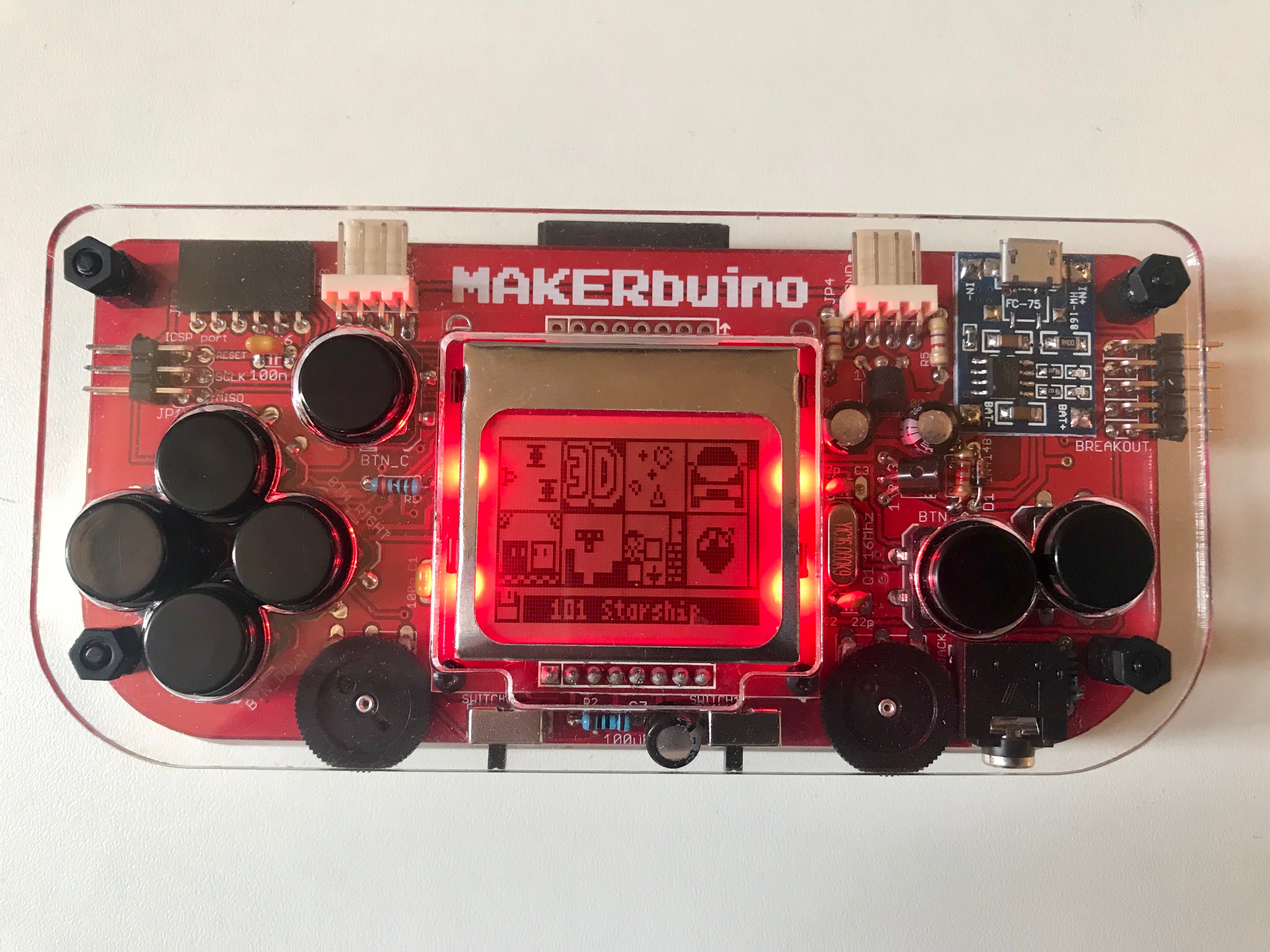
Tada!
