This is my first time ever soldering and doing this type of work, so I don’t know if this next statement is true or not, but I think I’ve gone beyond the point of return on my current kit
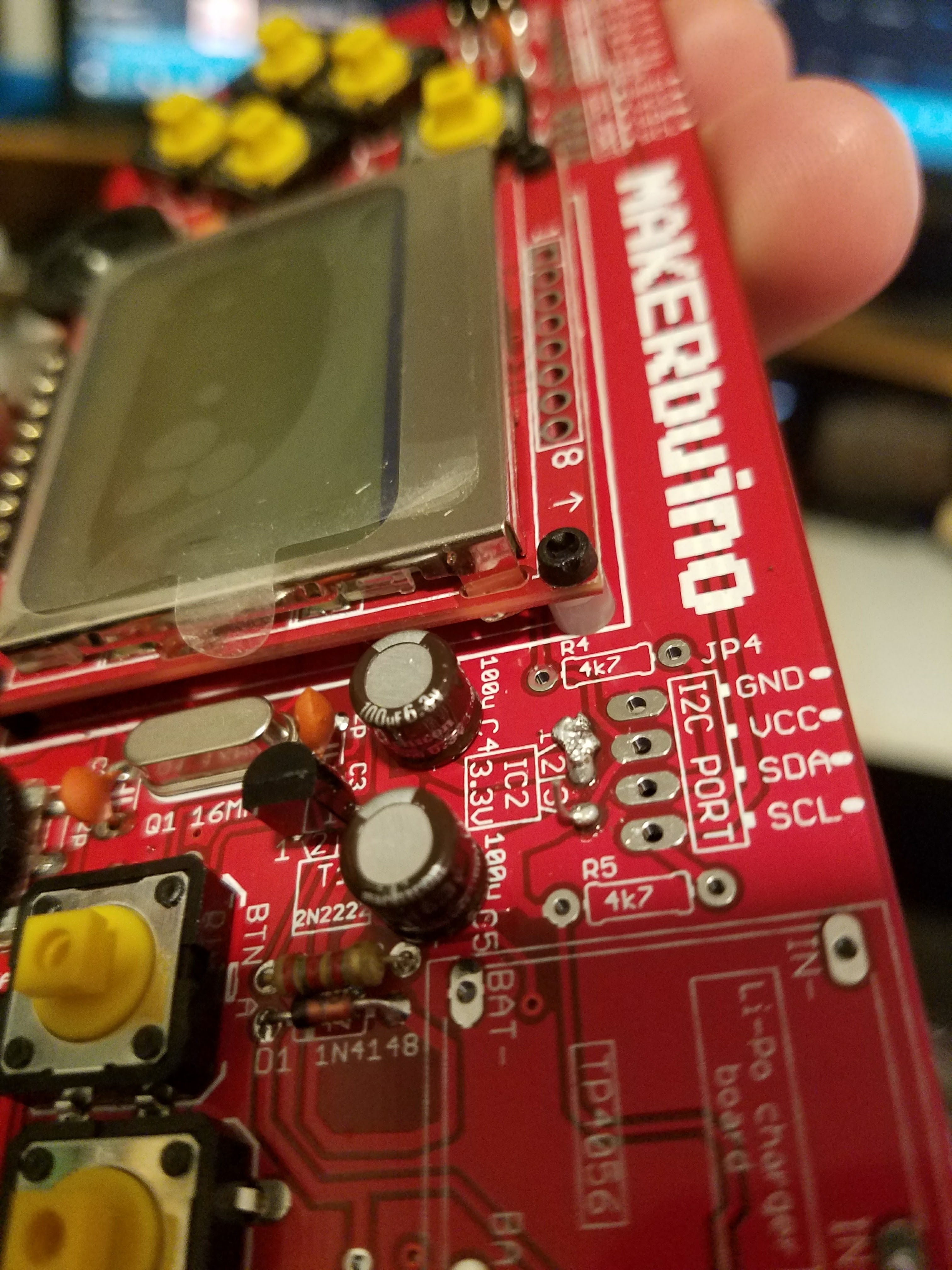
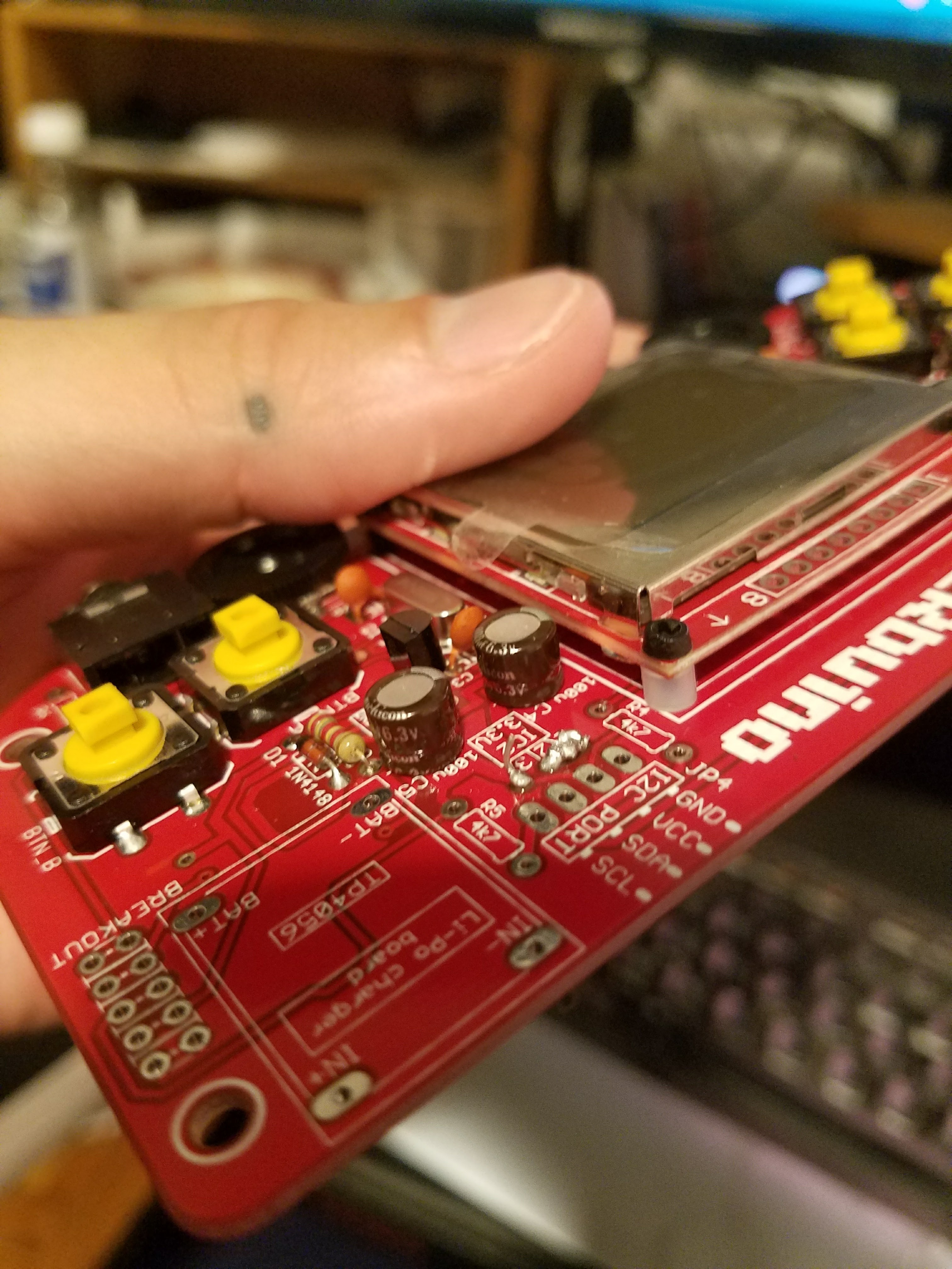
I put the regulator in the wrong way because my board is arranged differently than the tutorial. The regulator in the tutorial is placed well away from the 12c port. My regulator slots seemed to be too close to the 12c port, so I thought maybe I’m suppose to spin the regulator around on my board to fit it in. After seeing some completed projects I’ve realized that I should have put it in the correct way and the bent the piece down a little bit to fit it into the space.
So I attempted to undo my mistake by trying to remove the solder without the suction tool or copper wick… I’ve made a pretty big mess. The solder won’t even melt anymore. I’m definitely going to need a new regulator… Do I have to buy another kit in order to retry? I’m not sure if this is salvageable, but it was fun while it lasted
The board looks to be OK, just get your iron nice and hot and remove the excess solder.
Did you cut the regulator off the board? If so, if it still has long enough ‘legs’, it should still be OK to use if not damaged. Otherwise, visit your local electronics shop or online, this component is very cheap to replace just make sure you get the same one.
Tip: You need to make sure you’re soldering iron is clean by using a wet sponge and you need to use some solder flux on the solder joints. there is nothing wrong with using loads of flux.
But you need to be careful as too much heat on the solder pad could end up damaging the pcb board.
If you need a new 3.3v regulator then the part number is MCP1702-3302ET
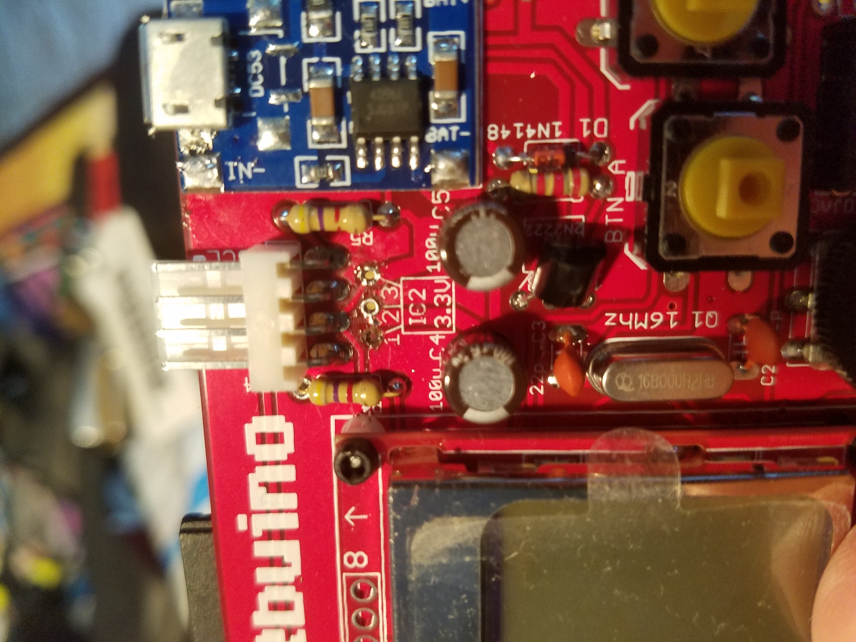
Thanks for the tip about the flux. Just picked some up with a solder pump and I’ve successfully cleared out the holes. I might have damaged the board though… the metal plate on the joint of one of the holes popped off.
The “metal cover” is called a “Pad”, these pads also connect both sides of the pcb board.
I’m guessing the pads on the other side of the board are still in good condition?.
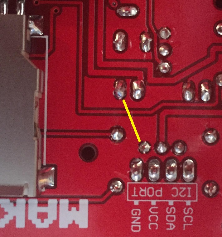
What you are going to have to do is pull out all you’re solder skills here
When you get the new 3.3 regulator, solder it so that the regulator faces down and solder the regulator
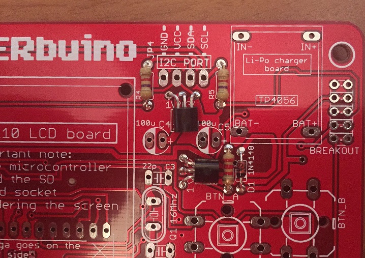
as you would normally following the MAKERbuino instructions, you will then have to solder a wire link
on the bottom of the pcb, this will then connect the broken ground pin (pin1) on top of the board back to the two
capacitors that the pin 1 ground also connects too. (this is bit with the broken pad).
Here is an image which shows you the two solder points you will need to solder a piece of wire too.
I’ve done the exact same thing for the exact same reason. The guide does not match the kit that I was set and all that it says for fitting the regular is “Be careful to turn it on the right side!”. Not being familiar with electronics and using this as a learning experience (as advertised), I’m not too happy that I now have a useless device. I have a solder sucker, but it’s not doing the job as far as I can tell (I’ve never had to use it before). I’ve let the iron get really hot and tried to apply to all 3 pins to allow for some movement but no luck. Just a few burnt fingertips trying to move it.
I wouldn’t advise any beginners to start working on this project until the guide has been completely rewritten so that it matches the kit that has been sent out and clear and accurate photos exist for each step, since this is what we need to follow. As a backer, I realize that the kit wasn’t too expensive, but I was honestly excited about this project and now it’s worthless if I cannot fix this honest mistake. All because I had to make a 50/50 guess as to how to what the “right way” was and, unfortunately, I made the wrong one.
I’m very disappointed this whole experience, to be honest. I was going to get another after this one for my partner, but I’m reluctant to hand over any more money to this project. Documentation is key and it feels out-dated and lacking in some key areas. I’m going to try desoldering again tomorrow, with a clear head, but I don’t have much hope that it’s going to work.
I only noticed at the stage where I had to turn it on for the first time. Nothing happened and I knew immediately that I must have made the wrong choice at this step. I’ve since looked up the piece online and found a simple diagram that showed the 1 2 3 numbers mapped to pins based on the top shape. This would have been perfect to see in the guide, to help others avoid wrecking their device too.
I managed to get the wrongly inserted regulator out, but I had to cut of the pins entirely to be able to remove it. This means that I have to get a new regulator somehow.
I’ve bit the bullet and paid for 10 (common minimum order quantity) from element14, which cost a lot more than they’re worth
As I said before, I’m very disappointed by this experience, but I’m still excited about it at the same time. Definitely conflicted. Hopefully the replacement works and I’ve not damaged the PCB in any way while attempting to remove the solders for the incorrectly inserted regulator.
I understand your disappointment and frustration. If it at all helps here is how the 3.3v regulator should be fitted, with the flat part of the regulator facing downwards onto the board. Are all your solder pads on the PCB board ok?.
I advise you to change your circuit silk layer for the next device you fabricate. I don’t know what software you use for PCBs, but with Eagle there are many libraries and usually this kind of transistor-like package are represented with a kind of D shape on the silk layer, which clearly indicates the direction.
By the way, are the schematics available somewhere?
I’m with you on this one @Tom. I don’t know why they changed the component layout and silk layer, If you look at the building guide then that shows you a perfect D shape (obviously an older version of the board), my only guess is that the component sat too high on the PCB and came in contact with the casing?
Yes, anything that outputs 3.3V and is capable of delivering more than 100mA should do the trick.
Just have in mind that LM317 cannot be used to regulate the Li-Po battery as it needs 3V difference between Vi and Vo (check out the datasheet, it’s very well written)


 My new regulator doesn’t come in for another week so I’ll let you know how it goes.