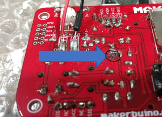
When soldering my makerbuino, I accidently burnt pin1 of the 2n2222 transistor. would it still work?
it would be a shame if I couldn’t fix it as I waited 3 months for my makerbuino. i watched a video where someone scratched of the plating of the PCB and attaches a solid wire to the copper that he scratched off. would this work in my context???
Please help!!!
my board
(link for video i watched)
(starts repairing around 8:50)
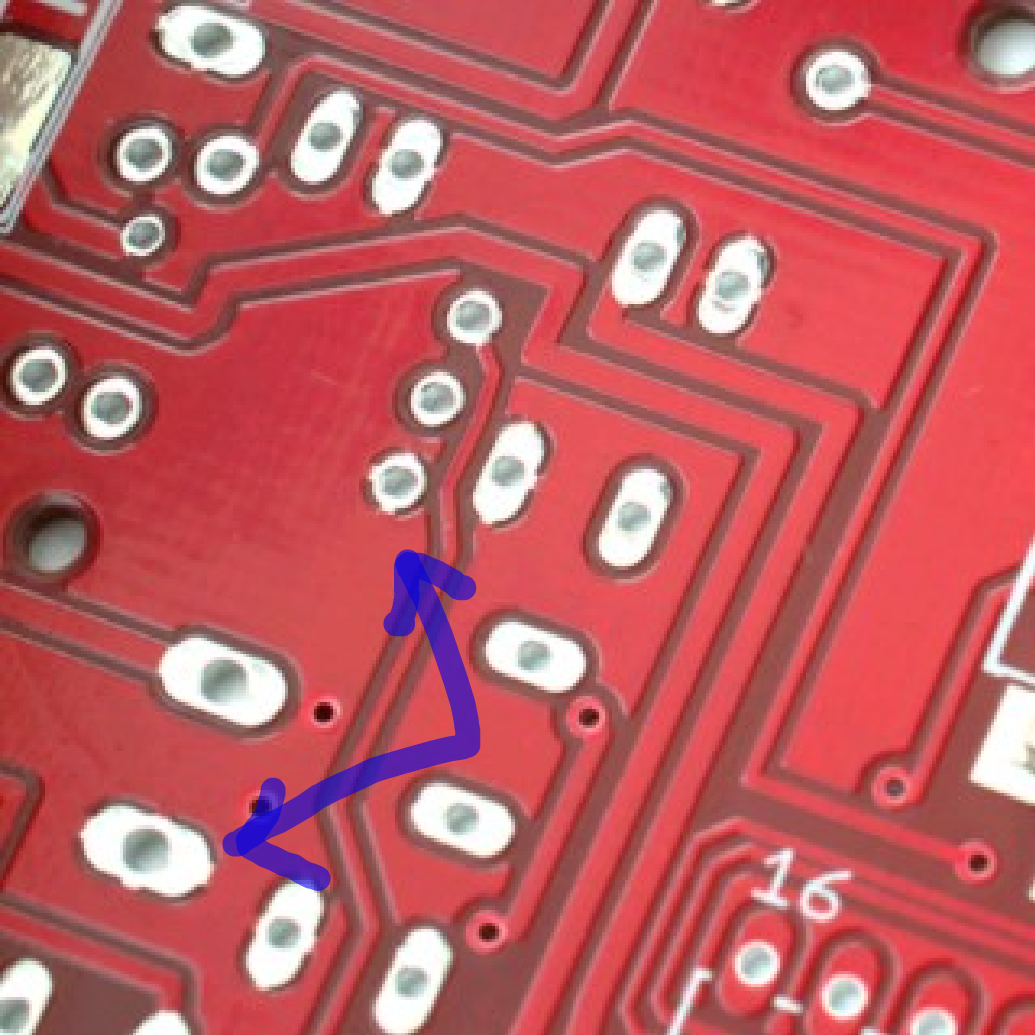
As @Jean-Charles_Lebeau said, you could run a wire to connect the pin with the missing pad to a pin that it’s connected to the same trace in the board. For example, in your case, you could run a wire between these two pins:
Or, as you saw in the video you shared, you can also carefully scrape the solder mask of the surroundings of the pad (where it connected to the missing pad) and apply solder between the scraped surface and the pin. A tiny piece of wire or component leg could be needed for the pin to reach.
Also, a tip: the more you apply heat to a pad, the more probable it is for that pad to dettach from the pcb, so heat things for as short as possible, as long as the solder melts properly.
About desoldering the pin headers for the screen, it normally is a little bit of a pain if you don’t have the proper tools. A solder sucker is a very nice tool for the job. Do you have one? If not, some solder wick (desoldering braid) should also work, but you’ll have to be careful of not overheating the pads. A bit of flux on the braid itself will make it much easier.
Good luck!
EDIT: I moved the thread to Support, for keeping things organized
Thanks for the reply,
but just to make sure it is pin1 for the transistor that is power/ground.
(I don’t want to mess up again)
ALSO:
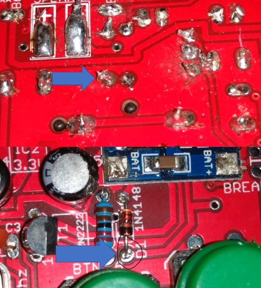
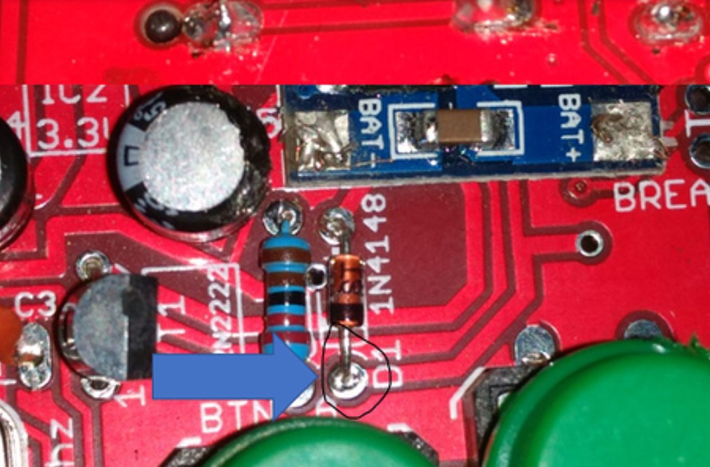
i just found out that the side of the diode with the black ring around it has also been destroyed. Since all the dark “lines” on the PCB confuse me i was wondering if someone with better experience than me can tell me which pin i should connect the diode to.
i was thinking of using a hot glue gun to keep the wire down, or would electrical tape be better?
(it’s hard to tell from the picture, but it is destroyed)
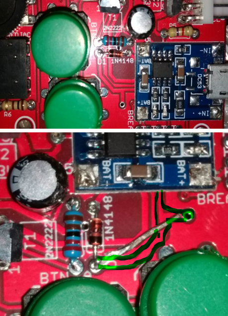
@MatthewDeDom, about the diode, there’s really no problem there: the connecting pad is on the side where the diode is, and the bottom side is really not connected (there’s only dark around the pin, meanning it was not connected to anything. As long as the top part is making contact, there should not be any problem:
@MatthewDeDom, as @Tom already asked, is everything working now? Do you still need a new microcontroller or did you manage to work this out (referring to this topic: Pins Broken On ATMega [SOLVED])