Hello, I am unsure about my LCD screen mounting. According to the new build guide, I have an “old screen”.
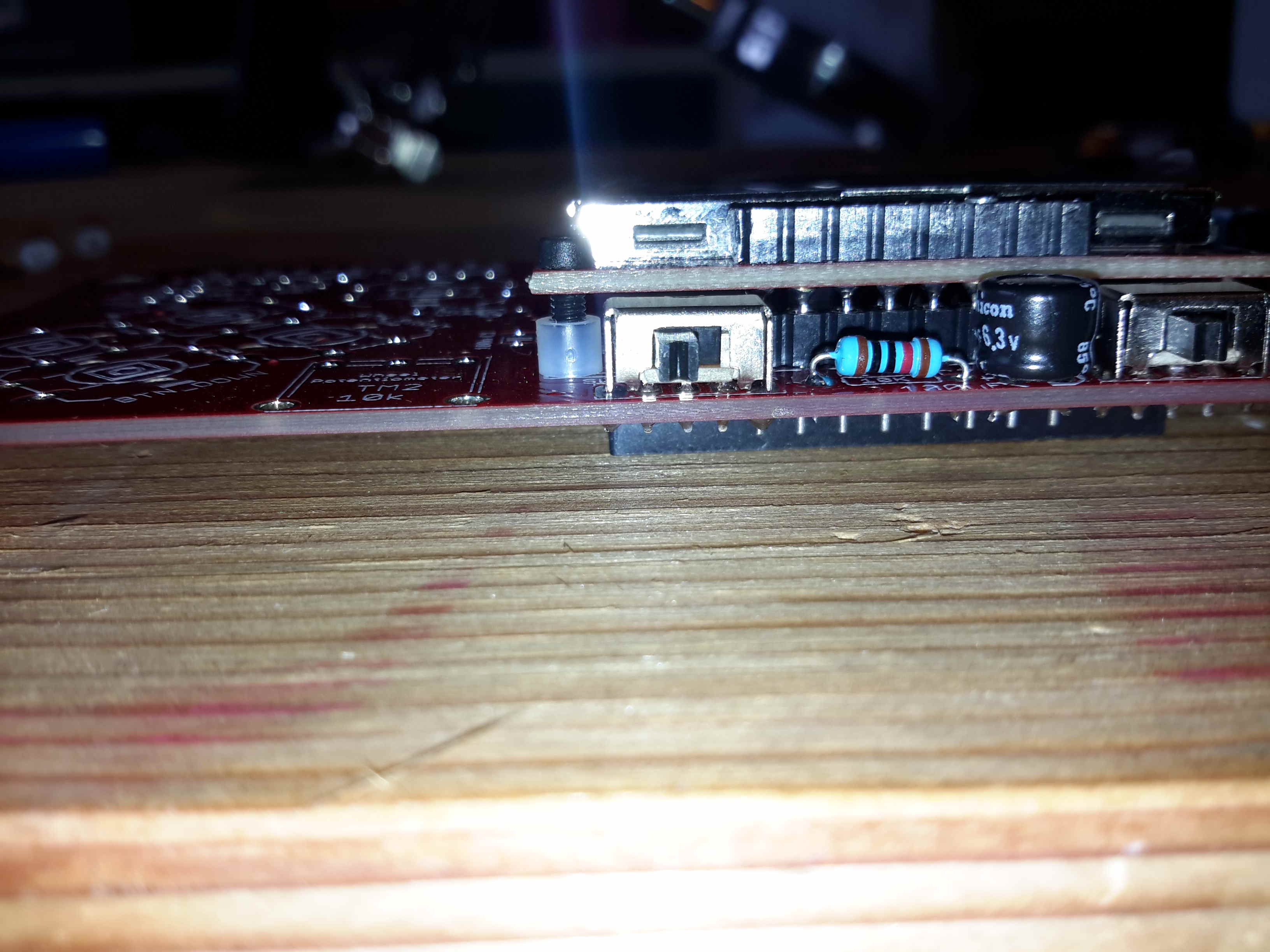
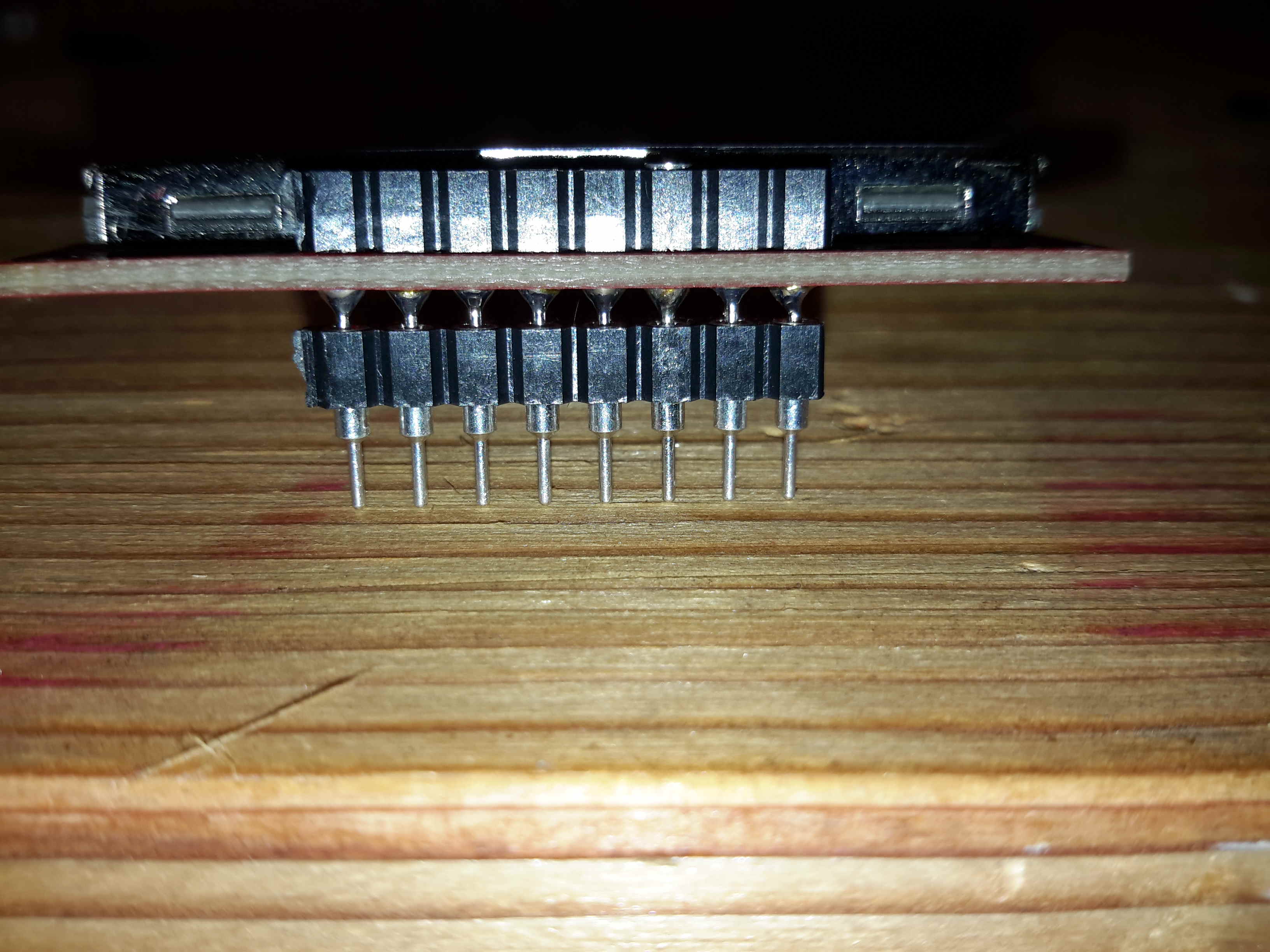
When I assemble the screen into the 8pin-female header and try to mount it with the spacer, the bolt rather doesn’t show out on the other side + there is much space between the screen-pcb and the spacer.
I think the problem is that the pins already soldered on the screen-pcb don’t fit enough into the 8pin-header.
One of the pins had more solder than the others, I already removed it and now it’s possible to mount it a bit.
But is it enough?
If you have a multimeter, you could check for continuity. Make sure you don’t have the battery plugged in and that the microcontroller isn’t installed. Place one probe on header on top of board and place the other probe on the corresponding pin of the header on the bottom side of the board. If there is a connection, you’ll either hear a beep or your meter will give you a reading (depends on what you set it to). No connection and no sound or reading remains as 0L.
Thanks for the reply.
I’m not so much concerned about the connectivity but more about the height of the screen. Will it collide withe the cover? And also, I have the problem that a can hardly fit the nut to the bolt because that only protrude so little on the lower side of the pcb…
I don’t really see too much solder, so the next thing I should try is to push the connector with a little bit more force. Mine was pretty stiff, and I had to push it harder that I thought would be necessary for it to completely connect. Could that fix it? Seems you only need another millimeter.
Thanks for the hints. In fact I had to push a bit harder so the pins go a bit deeper. It used my fingernails to push on the black plastic, and then it was easier. Still there was some gap greater than the spacers, but not so much, so i left the spacers away because the “clicked” around when shaking the buino. I think it’s fine now.
I have a second buino and with that one it fits well out of the box and goes down on the spacers. So this is probably in the tolerance of the screen you get
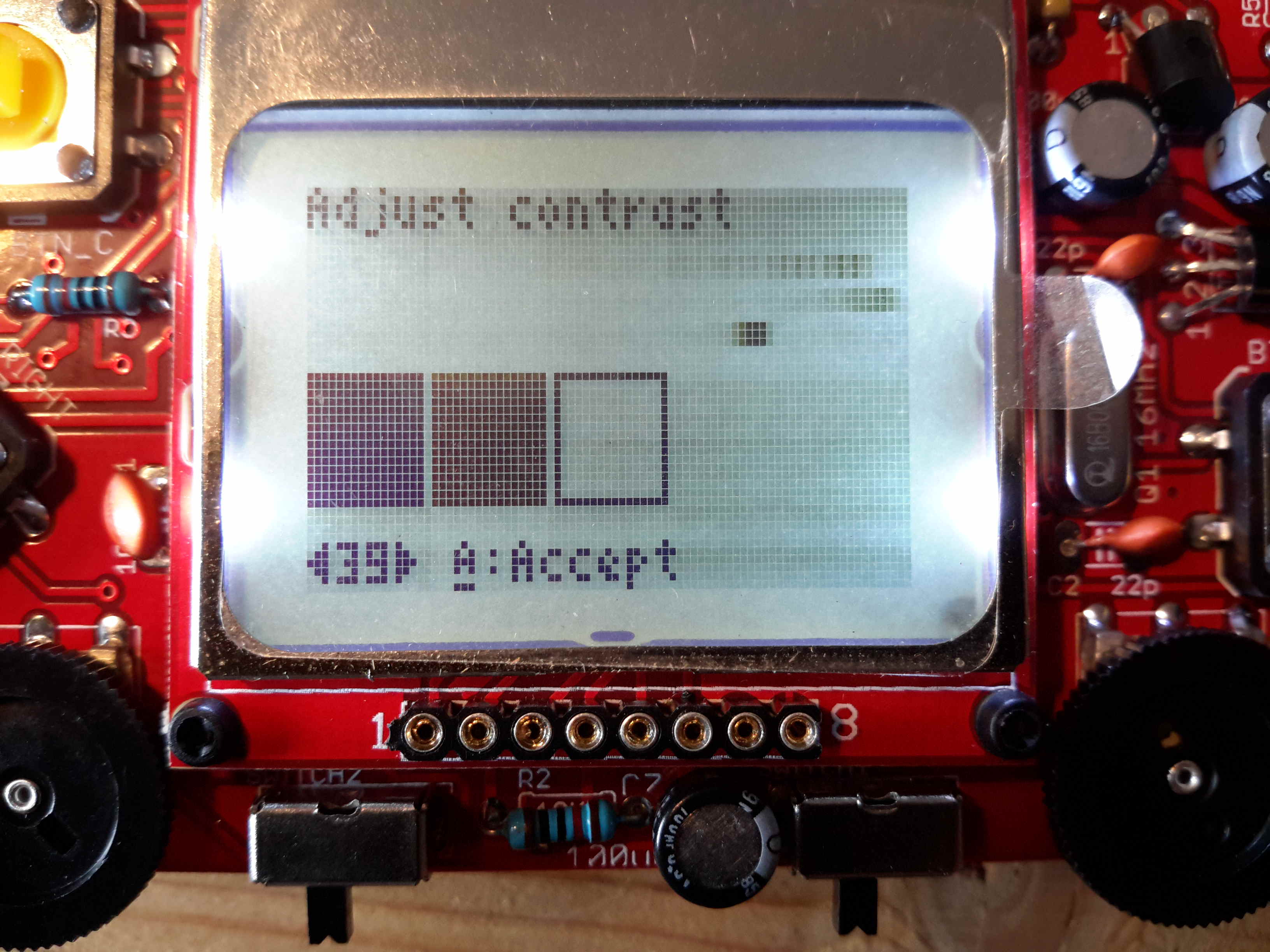
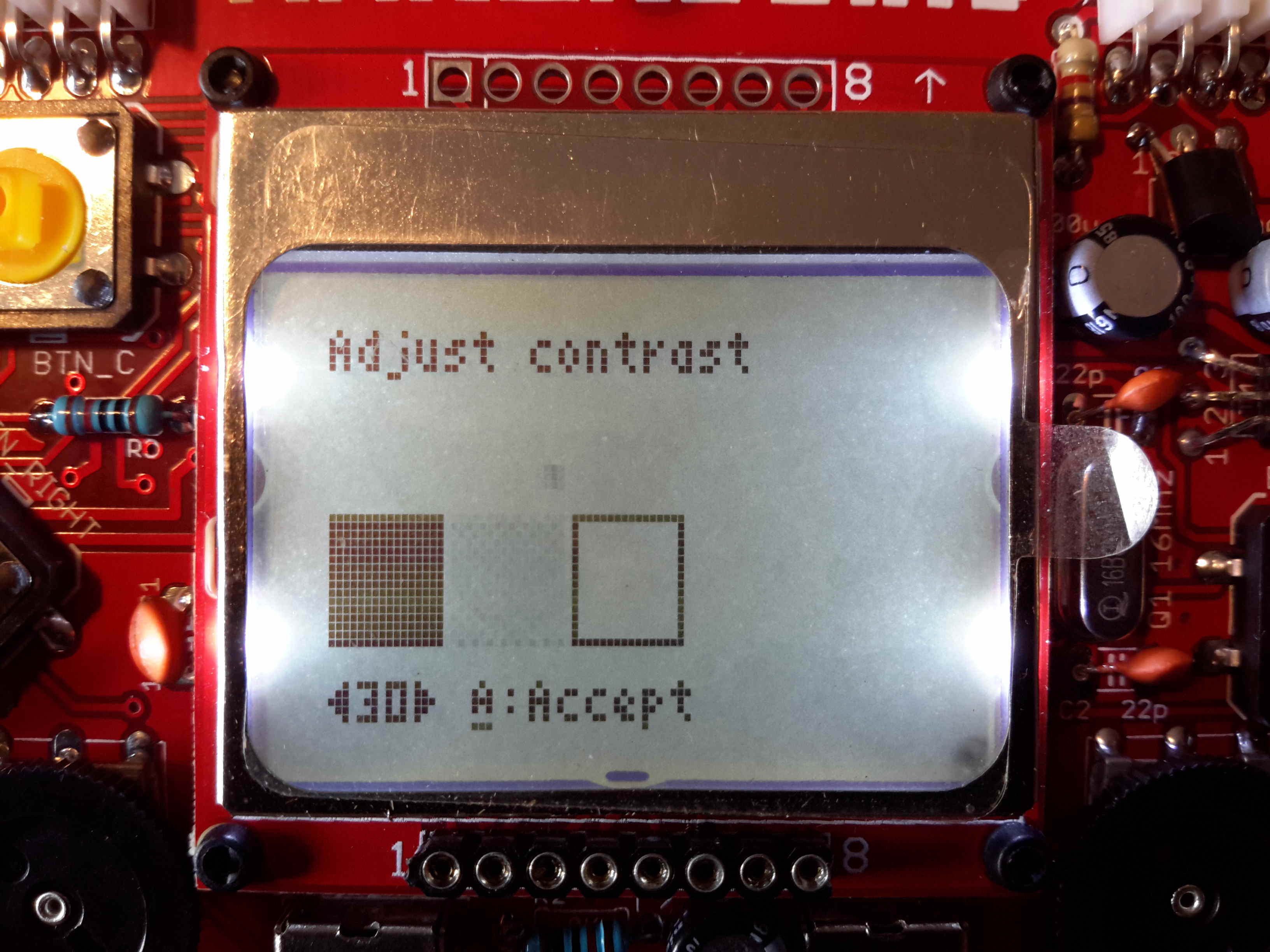
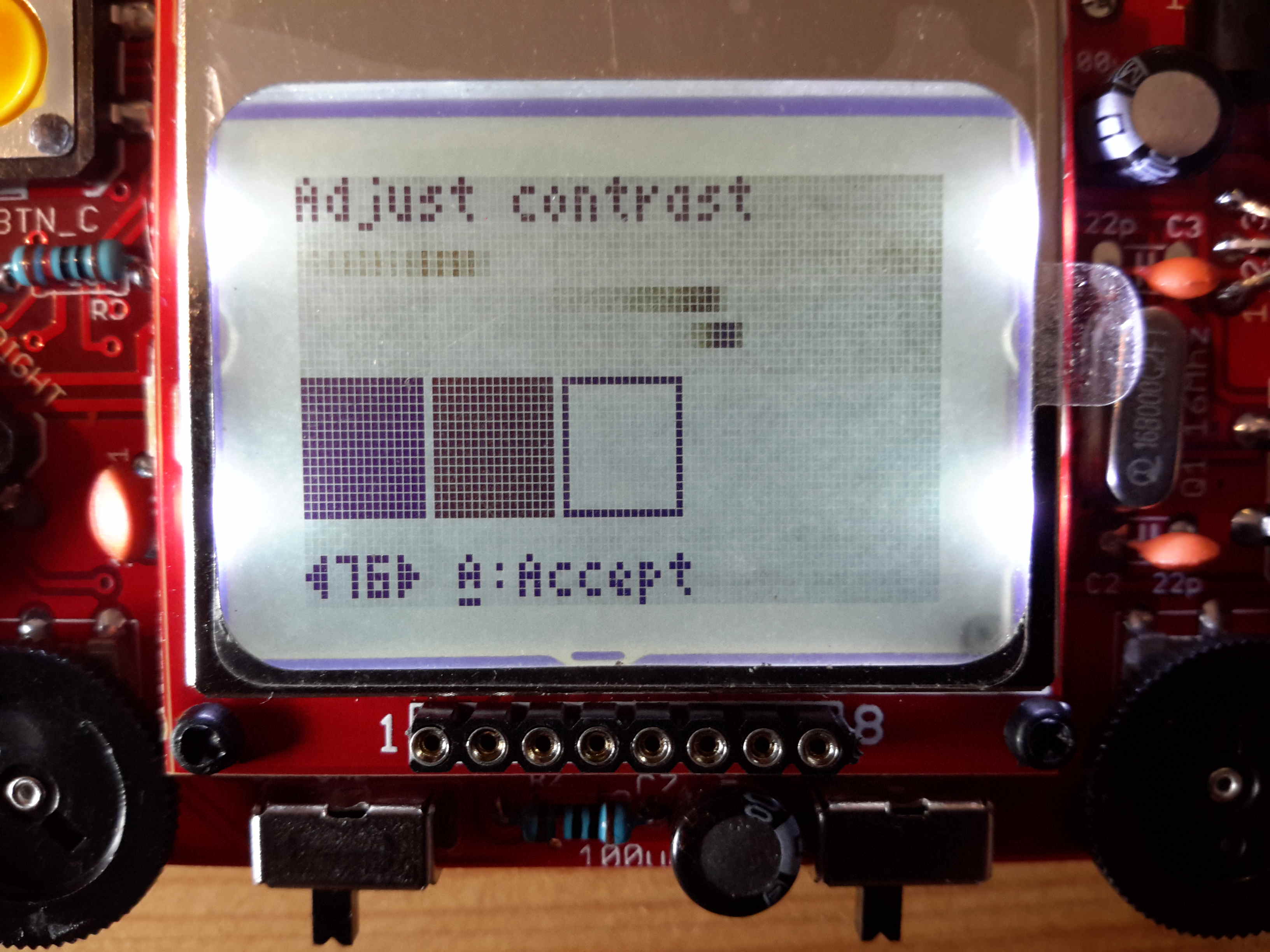
I have a second question now about the screen contrast settings. How should I set it up to be optimum.
With setting 39 I have a black, a grey and a blank box, but still some “pulsating” grey shades on the right side. When setting 30, the grey shades go all away and I have a clear background. But the middle box is almost also blank. How should I set it?
As said I have ordered more than one buino, so i tested with another display and on this one, the setting and grey shades were similar, but they were not “pulsating” as at the other one. Is this also tolerance of the lcd displays as they are all used ones? Or should I be worried?
Mine was like this, because of the massive blobs of solder on the screen pins it barely made contact, I resoldered mine much neater and it was fine after that
@vanG, kudos on figuring this out. You’ve just earned a couple of neat-o badges.
The contrast settings can vary from display to display, that’s why they have to be set for every individual display. It’s more of a personal preference, just adjust the contrast setting that looks the best to you.