Hello guys! I’ve just built my fresh MakerBuino and everything but the SD card is working.
The funny thing is that I’ve uploaded a “Hello Word” from ArduinoIDE and now the Buino plays it instead of the old Settings menu.
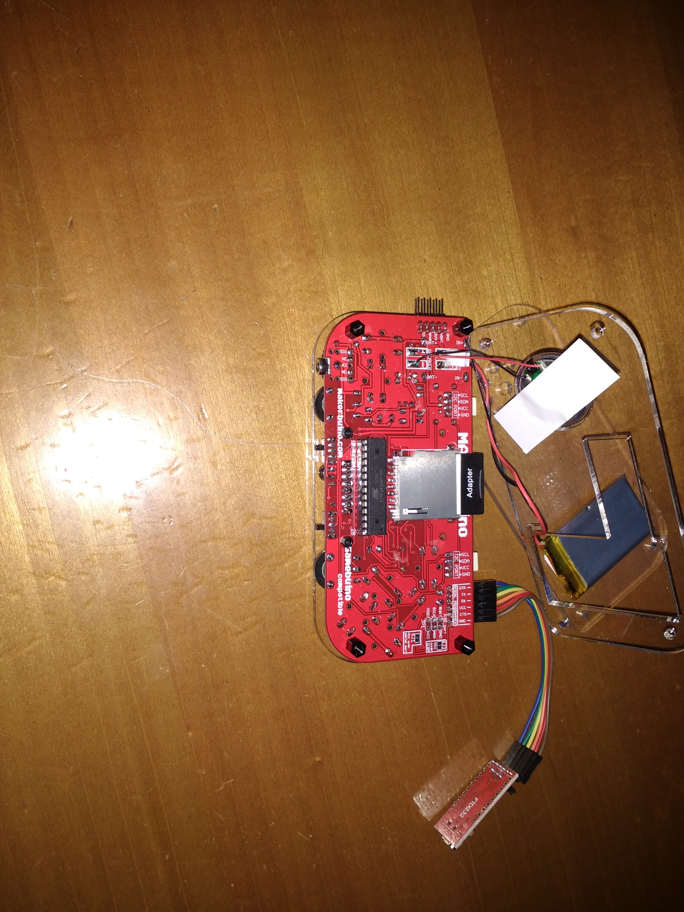
Long press C-button tells me flashing, but then nothing, nor the reset trick works; I’ve even tried to read the SD card via this
...
Gamebuino gb;
Sd2Card card;

void setup(){
  Serial.begin(9600);
  gb.begin();

  if (!card.init(SPI_HALF_SPEED, 1)) {
    gb.titleScreen(F("initialization failed"));
  } else {
   gb.titleScreen(F("Wiring is correct and a card is present"));
  }
}
There were default files like LOADER.HEX and games.
I even tried to format in FAT16 (with label MAKERBUINO) and then copy the game-collection zip provided here
Then the error occurs somewhere in between the sd card socket and the MCU. Have you checked your solder joints?
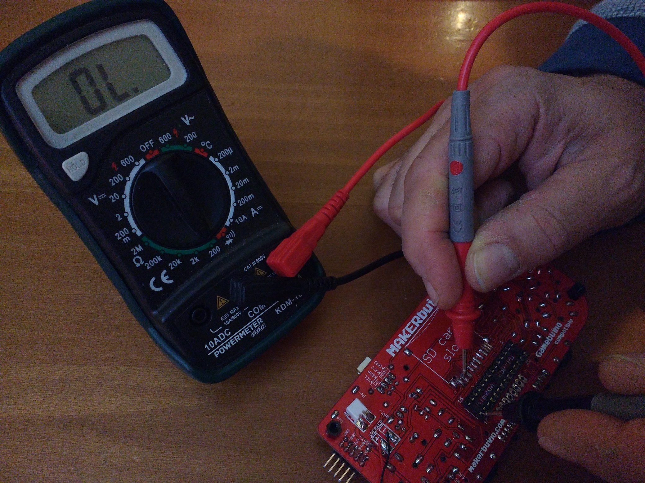
Do you have a multimeter to check for continuity?
Just test all of them
MAKERbuino switched off:
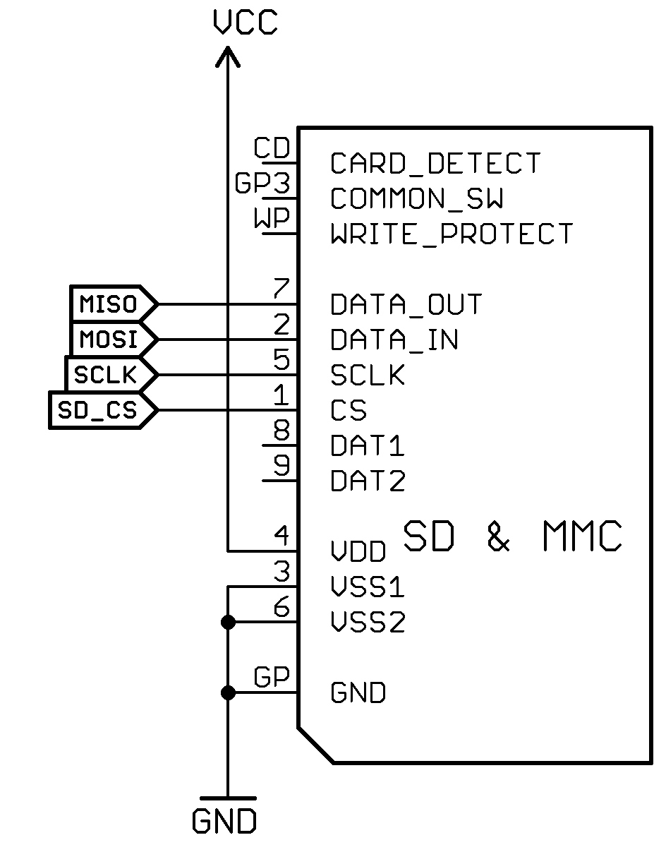
Continuity measurement between those pins:
Pin 1 (SD Card Slot SD_CS) and pin 16 (MCU SD_CS)
Pin 2 (SD Card Slot MOSI) and pin 17 (MCU MOSI)
Pin 5 (SD Card Slot SCLK) and pin 19 (MCU SCLK)
Pin 7 (SD Card Slot MISO) and pin 18 (MCU MISO)
Pins 3,6 and GP and any other GND pin
Those measurements should result in a very small to almost no resistance (~1Ohm or smaller).
Turn the MAKERbuino on and do a voltage measurement between pin 4 and GND of the SD card slot. The result should be 3.3V.
Welp, I’ll have to de-solder the display to access the MCU’s pin; and a little question: looking at the PCB, how are the pins numbered? (don’t want to get them wrong).
Why do you need to desolder the display?
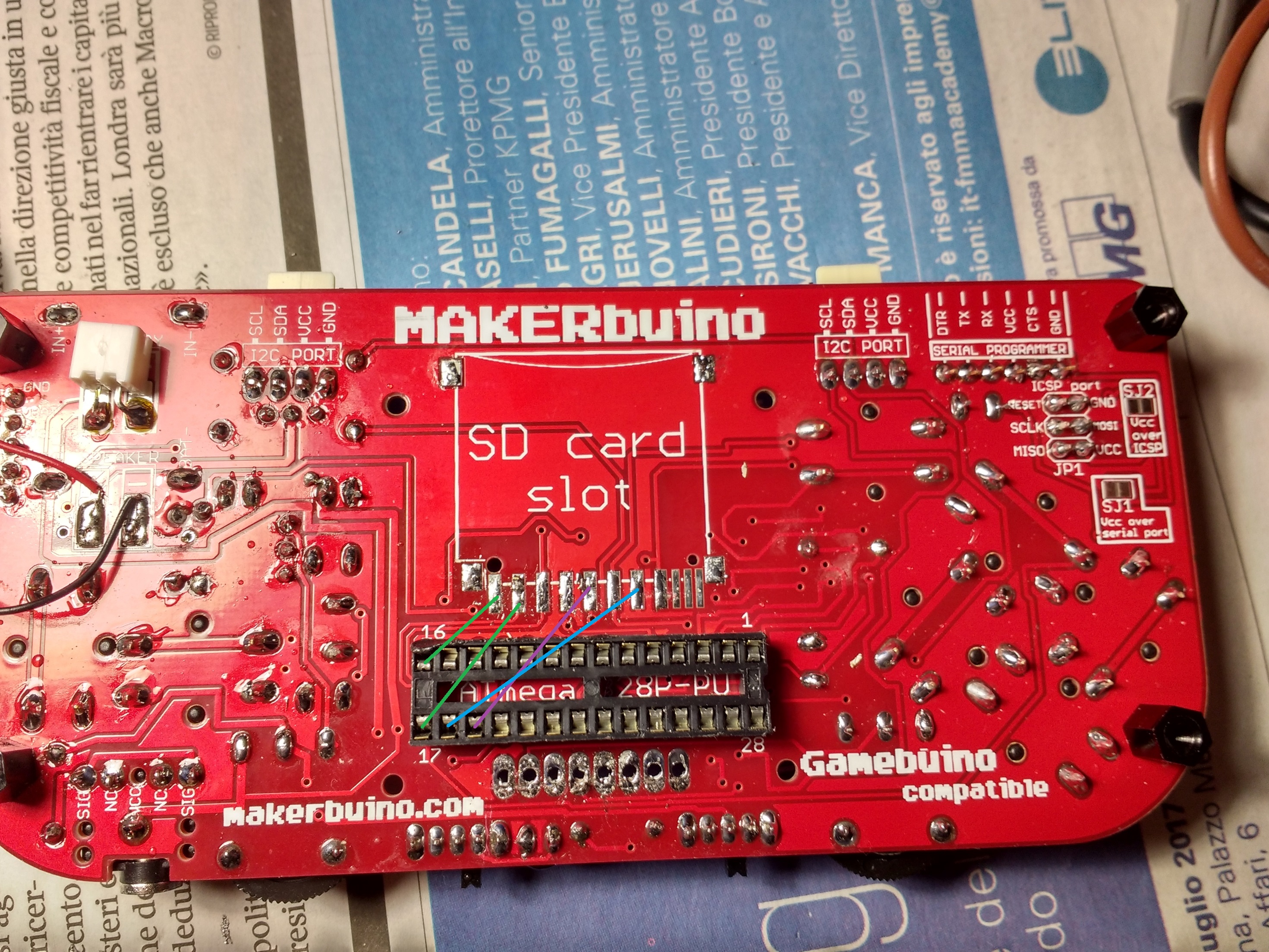
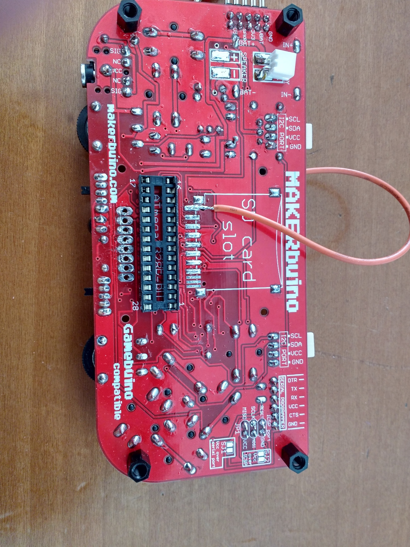
You can measure everything on the backside of the MAKERbuino as you can see in your first posts picture.
Counting pins is pretty easy. Pin 1 is always marked. Remember when you had to watch out for the notch on the ATmega? Turn your MAKERbuino 180° so that the notch is on the left side. You’ll see a small circle above the bottom left pin. This is pin 1. Just start counting the pins counter clockwise. There are numbers printed onto the backside of the PCB right next to the socket. You can use them as orientation
Good! I’ll test them later tonight, thank you for the support.
PS: I’m trying some game via ArduinoIDE upload, and it starts every time I play the Buino; it is saved on the EEPROM right? Can’t I try the same with LOADER?
Of course you can try it, but I guess you won’t see any game since you’re having trouble accessing the SD card.
But just out of curiousity go ahead and try it
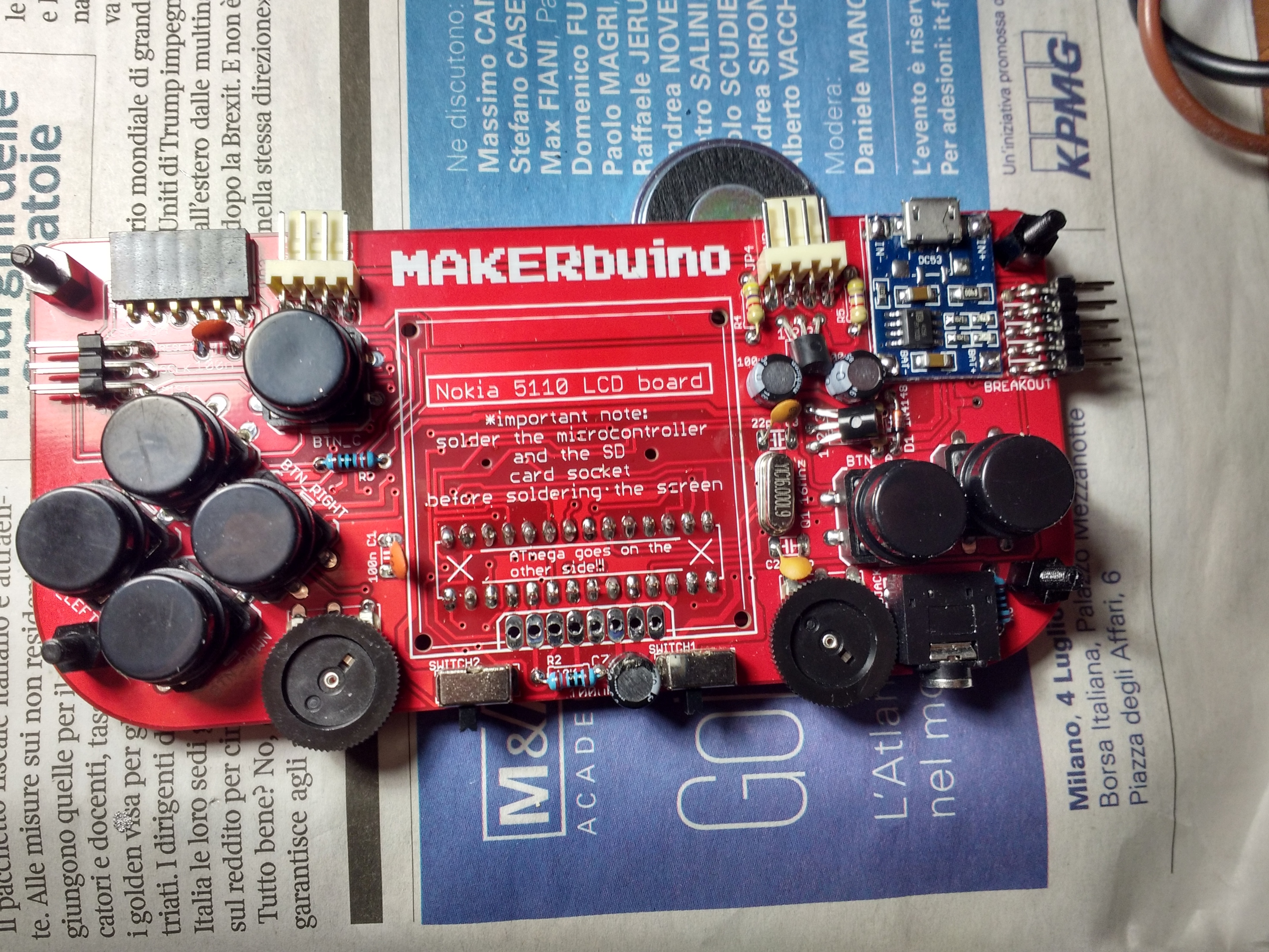
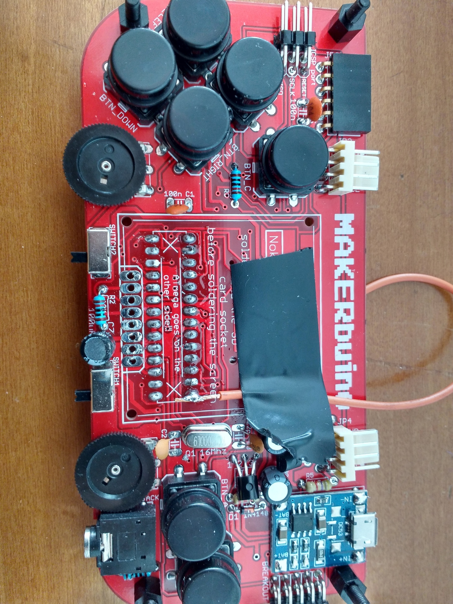
The 3.27V are fine. But there is absolutely no continuity between the MCU and the SD card slot? Not on a single line? Can you provide a close up picture of you SD card slot solder joints?
There is no need to desolder the components if you’re just doing some continuity tests. You have to be very careful als solder and desolder components multiple times can cause damage to your PCB.
But since you’ve already desoldered both components do another continuity test or, even better, a resistance measurement. Just put your probes onto the connected pins. There should be almost no resistance.
@0x1001,
I’ve received your email and am answering here.
The PCBs are all manufactured by the same company since the Kickstarter campaign and are all e-tested.
We did not have any PCB-related problems or complaints so far.
Please, test the continuity on all four data lines which connect the microcontroller to the SD card.
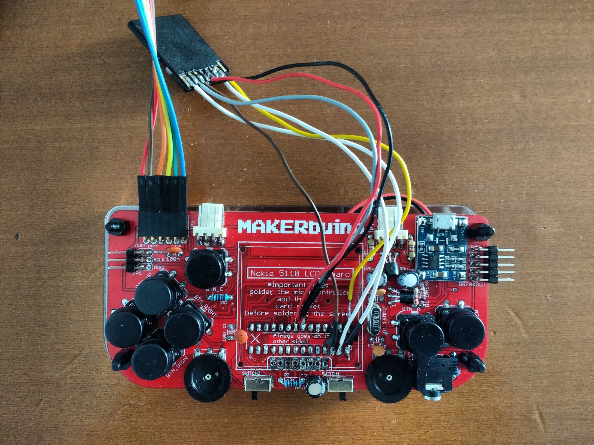
Are all SD lines open? How many of them do not have continuity? You can easily fix this by soldering a tiny wire between two soldering pads or by scratching the red paint from the PCB and soldering a tiny wire directly to the traces.
I don’t have continuity on any of the 4 pins between SD slot - MCU, everything is good but them and I can’t understand were’s the prolem
Tonight I’ll try with the wires
Edit: for now I’ve done a little test and it gives me little resistance