Only difference with mine was, at step 10, my battery connector was already fitted so I didn’t have to solder any wires on.
Now, I’ve triple checked that the micro controller is fitted correctly, the battery is of course the correct polarity (it was already fitted), and the contacts are not shorted/improperly soldered, but I may be wrong.
The device will not switch on at all. Is it possible that the battery is completely dead on arrival? Or have I just done something wrong.
It is possible the battery maybe low but both my kits had enough battery life to turn them on at this stage,
the only way to confirm this would be with a Multimeter?.
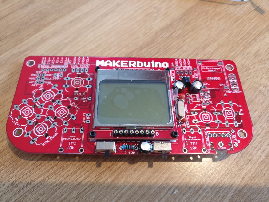
I’ve checked you’re images the best I can, the capacitors, resistor, switches all look to be fitted correctly…
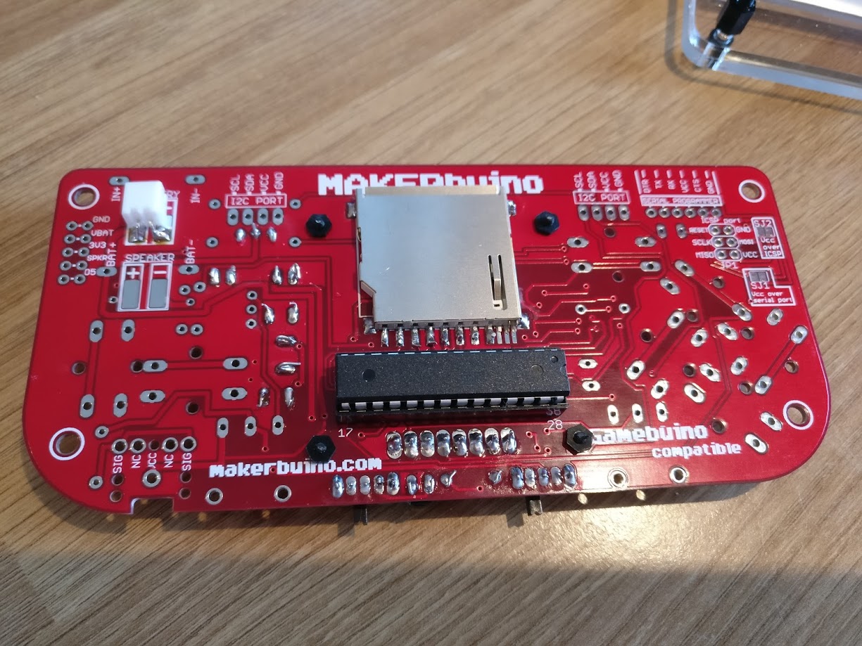
My only thought is the 3.3v regulator? are you sure you have fitted the 1702 regulator and not the 2n2222 transistor?
Just double check the markings on the other component?.
Thanks for your reply. I will try to get hold of a multimeter today and give it a test.
I have definitely fitted the 1702 regulator, and can’t see any issues with soldering, so other than the battery, I have no idea what could be going wrong…
I assembled up to step12 last night and have the exact same problem… Im in a summer house so don’t have a multimeter at hand, but I tried several small 3.7v batteries I brought along for a mini drone, and none of them would let me turn the unit on either.
Hi @tommyph1208 - Nice to know it’s not just me. I still can’t figure it out but really don’t think it’s the battery. Gonna go and pick up a multi meter today but think it’ll prove me right. Have emailed makerbuino in the hope they can offer some advice. Please let me know if you get any results.
It sounds like the boards do need some Multimeter probe tests carried out, especially checking the power pins 7,20,21 to the microprocessor. Can I advise you to remove the microprocessor from the board before you probe the board in case of any spikes from the Multimeter, to avoid any damage to the microprocessor?.
UPDATE*
It might also be advised to solder resistor R3 (10K) to the board in step 13 of the build guide.
I have just noticed that R3 is connected to the RESET line for the microprocessor, if the reset line is not pulled high then the microprocessor pin will be floating and could be in a constant RESET.
Thanks for the replies. I now have a multimeter, but am a complete newbie with one of these things.
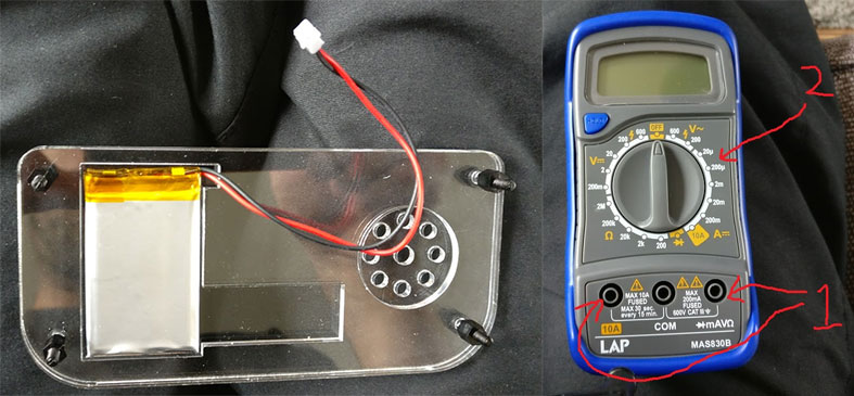
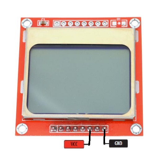
Can you please tell me how I can test this battery when it seems to be completely enclosed (see image below)?
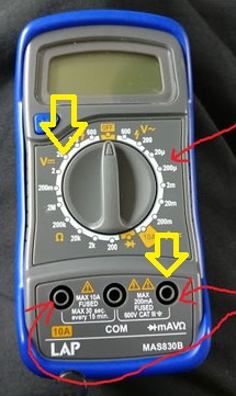
Also, I know the black wire on the multi meter needs to go in the middle (COM), but where should I put the red wire (1), and where should I turn the knob to (2)?
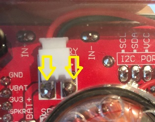
Don’t be sorry for you’re question, I’m happy to help. To test the battery voltage, you can probe the back of the battery connector, if not then you can plug the battery connector into the battery connector on the board and check the battery voltage on the solder joints, here is an image which shows what I mean.
You will need to set you’re Multimeter to the following: plug the red lead into the right plug and turn the knob to position 20 - the yellow arrows show the positions:
@amilanvega Very strange that you don’t get anything? If that is the case, then maybe you will need to complete the build of the Makerbuino, plug in the battery and put the Makerbuino on charge?. See if the battery will charge and see if you can then turn on the device.
Completed step 13 and still not switching on, @bitfogav. Do you think I should continue to build it to the end and then see what happens? Getting a bit annoyed with it now!
I wouldn’t complete the board at this stage, but it’s up to you?.
I would be checking the powers and grounds on the microprocessor and screen.
If that’s something you want to try then remove the microprocessor from the board and connect the battery, switch both switches to the left, so that the makerbuino is in a switched on state.
Set you’re Multimeter and wires the same as before.
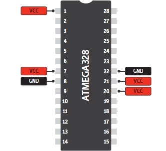
Now check the microprocessor connector on the board, you need to check the voltage on these pins:
Put the Multimeter black wire on pin 22, and with the red wire check pins 21 and 20.
now move the Multimeter black wire to pin 8 and red wire on pins 7 and 1.
Record the voltages that you get on every pin.
And check these pins on the screen:
Multimeter black wire on pin 8 and red wire on pin 6, record the voltage.