@amilanvega Very strange that you don’t get anything? If that is the case, then maybe you will need to complete the build of the Makerbuino, plug in the battery and put the Makerbuino on charge?. See if the battery will charge and see if you can then turn on the device.
Yes 3.92v is what I would expect. did you try step 13 and fit the R3 resistor?
Not yet. Will try that now that I know the battery is fine, and get back to you. Thanks.
Completed step 13 and still not switching on, @bitfogav. Do you think I should continue to build it to the end and then see what happens? Getting a bit annoyed with it now!
I wouldn’t complete the board at this stage, but it’s up to you?.
I would be checking the powers and grounds on the microprocessor and screen.
If that’s something you want to try then remove the microprocessor from the board and connect the battery, switch both switches to the left, so that the makerbuino is in a switched on state.
Set you’re Multimeter and wires the same as before.
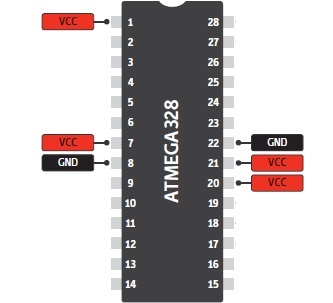
Now check the microprocessor connector on the board, you need to check the voltage on these pins:
Put the Multimeter black wire on pin 22, and with the red wire check pins 21 and 20.
now move the Multimeter black wire to pin 8 and red wire on pins 7 and 1.
Record the voltages that you get on every pin.
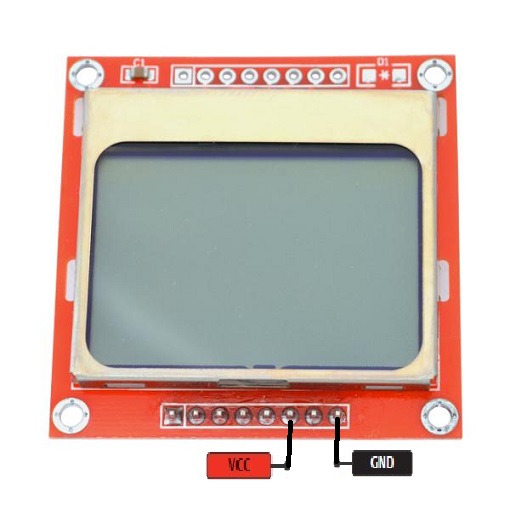
And check these pins on the screen:
Multimeter black wire on pin 8 and red wire on pin 6, record the voltage.
3 Likes
Ok guys, this is pretty embarrasing… But tonight I started triple checking everything, desoldered a bunch of components to make sure they were correct and… Well, turns out one of the pins on my ATMEGA socket was bent when I put it inthe first time, and so, wasn’t soldered properly… I had to desolder the entire socket and take it out to fix the pin (what a nightmare). Good thing is that my Makerbuino now works! Yay!
1 Like
Okay @bitfogav , here’s my recordings based on what you asked me to provide:
8 7 - 3.29v
8 1 - 3.26v
22 21 - 3.29v
22 20 - 3.29v
screen - 3.92v
I also tried putting the micro controller back in again (checking all pins) but no luck.
Thanks.
Hi @bitfogav
Just tagging you again in case you missed my last msg containing the voltages. Appreciate you’re busy so just making sure.
Thanks.
@tommyph1208 great stuff, glad you got your makerbuino working 
@amilanvega Sorry for getting back to you late but I’m back at work this week so don’t get much time.
You’re voltage results are perfect!, shows your microprocessor and screen have got power and grounds.
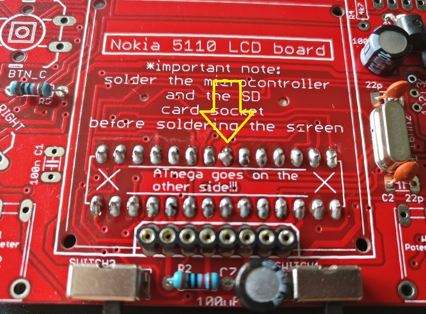
I’ve had another look at you’re makerbuino images and I can’t see anything wrong. The only thing I cant see is the solder joints underneath the screen for the microprocessor connector?.
Can you remove the screen and check the solder joints and double check all the other solder joints too, if you have too maybe run the soldering iron over them all again with some solder just to make sure?.
The only other things that are left is the connections between the microprocessor data lines and the screen, or even the software loaded onto the microprocessor?.
But there is also the possibility that after all this the microprocessor or screen could be faulty.
1 Like
Thanks again, @bitfogav.
I’ve taken some more detailed pics of the soldering points without the screen attached:
https://photos.app.goo.gl/YcmVTWsb8rqnbW9f1
What would then be my options for testing the connections between the MP data lines/screen, the software, the MP itself or the screen itself?
Lots of people seem to be posting on the forum saying that MakerBuino’s contact is very bad.
Thanks for the images. Looking at the one with the pic connector, this solder joint doesn’t look right?
1 Like
My first build Saturday evening went well, failing around 20 hours later. This was rectified with the C button. However, I have built my second unit tonight, and it does not boot up. Voltages to the micro and LCD are good. However, there is no 16MHz sine wave on each side of the crystal on this non-functional board. The working board has a nice 16MHz sine wave on each side of the crystal.
It would appear that my microcontroller is not functional, or maybe not programmed.
1 Like
You could try putting the ATMEGA chip into the other unit, this way you can ensure the chip is functioning. My best guess would be the crystal component itself is broken, I’m sure if you ask the makerbuino guy he can send you replacements… or you could grab them at a local hardware store.
1 Like
Swapping the micro over between the working and non working devices was going to be the next thing I try (will do that when I get home tonight). That will tell me if the fault stays with the board, or moves with the micro.
Well, I have some good news and some bad news. the good news is that my second board and components is fine. The bad news is that the microcontroller is faulty. The fault moved with the microcontroller.
I will send an email to Albert and tell him the bad news.
1 Like
Let Albert know and I’m sure he’ll send you a new one.
2 Likes
@wojtek and @bitfogav, thank you for your effort and helping @amilanvega out!
I really appreciate the effort you’re putting into this and your activity on the community forum.
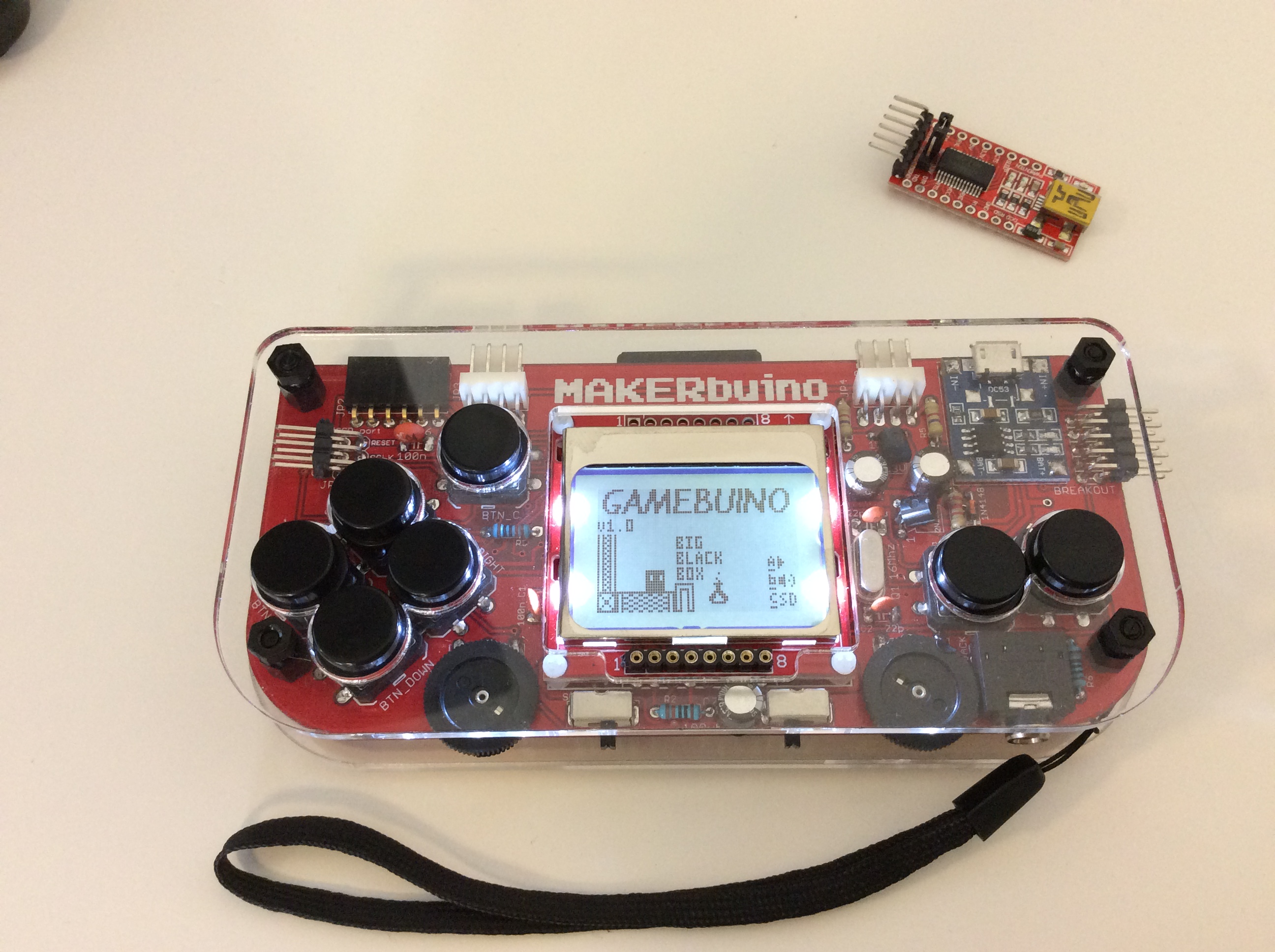
@tommyph1208, I am really glad that your MAKERbuino is working and would love seeing it work (pics or it didn’t happen )
I’ve spoken with @Eddie and will send him a replacement micro this Thursday.
@amilanvega, please don’t give up, we will help you build your MAKERbuino.
What is the status of your build? Have you managed to make something work in the meantime?
1 Like
Hi! I have the same problem as @amilanvega, only difference is that i have different measurements. My multimeter showed around 2.7v. Is this high enough voltage? Is microcontroler in inventors kit loaded with software or do i have to program it?
Thanks!